
Crowbar Speaker Protection

A crowbar circuit is potentially destructive - if th e circuitry only has a minor fault, it will be a major fault by the time a crowbar has done its job. It is not uncommon for the crowbar circuit to be destroyed as well - the purpose is to protect the device(s) attached to the circuit - in this case, a loudspeaker. There`s really nothing to it. A resistor / capacitor circuit isolates the trigger circuit from normal AC signals. Should there be enough DC to activate the DIAC trigger, the cap is discharged into the gate of the TRIAC, which instantly turns on.
hard. A TRIAC has two basic states, on and off. The in-between state exists, but is so fast that it can be ignored for all intents and purposes. The BR100 DIAC (or the equivalent DB3 from ST Microelectronics) is rated for a breakdown voltage of between 28 and 36V - these are not precision devices. Needless to say, using the circuit with supply voltages less than around 40V is not recommended, as you will have a false sense of security.
The supply voltage must be higher than the breakdown voltage of the DIAC, or it cannot conduct. Zeners cannot be used as a substitute for lower voltages - a DIAC has a negative impedance characteristic, so when it conducts, it will dump almost the full charge in C1 into the gate of the TRIAC. This is essential to make sure the TRIAC is switched into conduction. The TRIAC is a common type, and may be substituted if you know the specifications. It`s rated at 12A, but the peak current (non-repetitive) is 95A, and it only needs to sustain that until the fuse (or an output transistor) blows.
A heatsink is preferred, but there is a good chance that the TRIAC will blow up if it has to protect your speakers, so it may not matter too much. The 0. 47 ohm resistor is simply to ensure that the short circuit isn`t absolute. This will limit the current a little, and increases the chance that the TRIAC will survive (albeit marginally).
Feel free to use a BT139 if it makes you feel better - these are rated at 16A continuous, and 140A non-repetitive peak current. The peak short circuit current will typically be about 90A for a ±60V supply, allowing ~0. 2 ohms for wiring resistance and the intrinsic internal resistance of the TRIAC, plus the equivalent series resistance of the filter capacitors.
That`s a seriously high current, and it will do an injury to anything that`s part of the discharge path. Such high currents are not advised for filter caps either, but being non-repetitive they will almost certainly survive.
Apart from the obvious requirement that you don`t make any mistakes, construction is not critical. Wiring needs to be of a reasonable gauge, and should be tied down with cable ties or similar. C1 must be polyester. While a non-polarised electrolytic would seem to be acceptable, the circuit will operate if the capacitor should dry out over the years. This means it will lose capacitance, and at some point, the crowbar may operate on normal programme material.
This would not be good, as it will blow up your amplifier! Make sure that all connections are secure and well soldered. Remember that this is the last chance for your speakers, so it needs to be able to remain inactive for years and years - hopefully it will never happen. The circuit doesn`t have to be mounted in the amplifier chassis - it can be installed in your speaker cabinet.
Nothing gets hot unless it operates, at which point no-one really cares - it just has to save the speakers from destruction once to have been worthwhile. Remember that the crowbar circuit absolutely must never be allowed to operate with any normal signal.
A perfectly good amplifier that triggers the circuit because of a high-level bass signal (for example) will very likely be seriously damaged if the crowbar activates. To verify that no signal can trigger it, you may want to (temporarily) use a small lamp in place of R2, and drive the amp to maximum power with bass-heavy material.
A speaker does not need to be connected. If the lamp flashes, your amp would have been damaged. If this occurs, you may want to increase the value of C1. Note that bipolar electrolytics should never be used for C1, because they can dry out and lose capacitance as they age. This could cause the circuit to false-trigger. 🔗 External reference
Related Circuits

Connect a transformer to the motor phase line when the induced voltage is zero volts. In cases of serious imbalance in one, two, or three phases, the transformer’s induced voltage increases rapidly, which leads to an immediate rectification of...
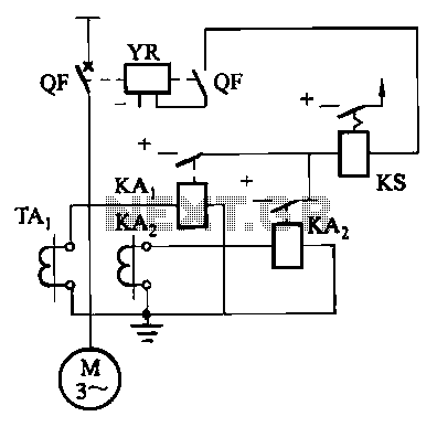
Figure 4-52 (a) illustrates the two-phase wiring for direct current (DC) operation, while Figure 4-52 (b) depicts the two-phase current differential wiring for alternating current (AC) operation. The schematic in Figure 4-52 (a) represents a two-phase wiring configuration suitable for...
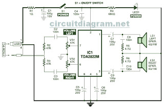
This is the circuit diagram of a USB-powered computer speaker, commonly referred to as multimedia speakers for PCs. The circuit features a single-chip design, operates on a low-voltage electrical power supply, is compatible with USB power from computers, and...
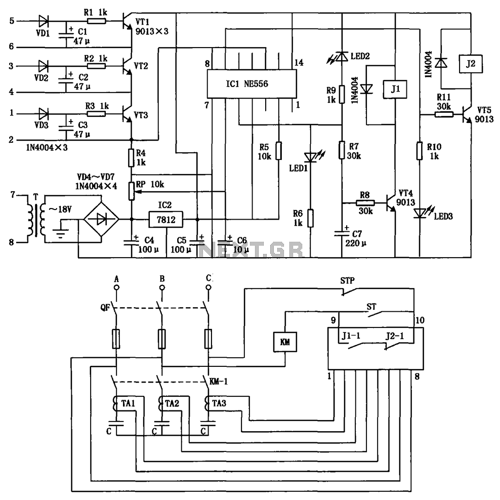
The circuit depicted is utilized in a power supply system to promptly disconnect the power supply in the event of an over-voltage condition during either the grid's on or off phase, thereby protecting the power capacitors. This circuit serves a...

A simple 5 Volt regulated power supply unit (PSU) featuring overvoltage protection. This 5 Volt regulated power supply is designed for TTL and 74LS series integrated circuits. The 5 Volt regulated power supply unit is an essential component in electronic...
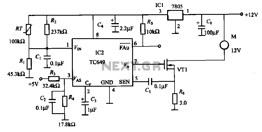
A motor is a heating device that can overheat, often due to accidents or overloads caused by excessive coil winding temperatures. The TC649 motor overheating protection and drive circuit, depicted in FIG. 1-9, utilizes an NTC thermistor (RT) positioned...