
BA1404 5W FM Transmitter Power by Fmuser Guanghzou China office

The miniature wireless FM microphone circuit is designed with simplicity and efficiency in mind, utilizing only four main components to achieve its functionality. The core of the circuit is a high-frequency oscillator, which is crucial for generating the FM signal. The transistor junction capacitance plays a pivotal role in determining the oscillator's frequency, with a capacitance value in the range of 2 to 3 picofarads. This small capacitance allows for a compact design while maintaining effective operation within the desired frequency range.
The coil design is critical for the circuit's performance. A coil with a diameter of 5mm and 7 turns is recommended to optimize the inductance required for stable operation. The use of a condenser microphone enables the modulation of sound signals into frequency variations, which is essential for FM transmission. The circuit's design must ensure that the resistance values are carefully chosen to maintain the balance between current draw and transmission range, with a specified range of 300 to 500 ohms to optimize performance while keeping power consumption below 1mW.
The choice of transistor is also significant, as it must have a cutoff frequency greater than 300MHz to ensure reliable operation at the desired frequencies. The 2SC3358 transistor is a suitable choice for this application due to its high-frequency capabilities, which contribute to improved signal stability and extended transmission distances.
The inductance is split into two coils, L1 and L2, which must be wound uniformly to ensure consistent performance. L1 consists of 4 turns of 0.5mm enameled wire, while L2 has 3 turns. This configuration helps in achieving the desired inductance while maintaining a compact form factor.
For the antenna, a length of 10cm soft wire is sufficient for effective transmission. It is important to note that the antenna's performance can be influenced by physical interaction, such as touching, which may lead to frequency changes. However, the circuit exhibits stable performance when positioned in a fixed location.
Overall, this miniature FM microphone circuit is designed for versatility and can be housed within a small ink bottle or integrated into a pen. The use of compact batteries, like the A13, allows for portability, while the inclusion of a switch facilitates user-friendly operation. The design is well-suited for applications requiring a compact, efficient, and reliable wireless audio transmission solution.Circuit with a few components, only four to form a miniature wireless FM microphone, a more stable operating frequency, firing range of more than 10 meters, 1. 5V supply, the current less than 0. 5mA, so that the microphone energy also rare, 3V supply when the distance of up to 30 meters. Circuit shown in Figure, BG and L and the transistor junction capacitance high-frequency oscillator circuit composed of transistor junction capacitance of about 2 ~ 3P, make the FM frequency falls within the scope of the coil should be 5mm in diameter around the core 7 of a circle, then by the condenser microphone modulated with a frequency of vibration when the signal generator frequency offset, to achieve FM. The emission current distance and the size of the emission control work, the resistance can not come too big nor too small, between 300 and 500 in Europe, less than 1 mW power.
BG when selected, the pipe must be greater than fT 300MHz, such as high frequency with 2SC3358 tube, the frequency is more stable, longer distance will be more. Inductance L divided into two coils around the system, but to be the same around, L1 0. 5mm enameled wire with a diameter of 5mm in diameter and 4 turns around the skeleton, L2 3 turns around.
Antenna can be 10cm long soft wire, use hand to touch the antenna will affect the frequency of changes. When used at a fixed location is very stable. This circuit can be put into such a small ink bottle, the kit can be installed in the pen, battery or more small batteries A13, but note that a small-capacity battery plus a switch.
🔗 External reference
Related Circuits

The circuit presented is an economical smooth variable power supply that provides an output range of 0V to 24V. It incorporates all necessary controls and short circuit protection while maintaining acceptable regulation and a ripple-free output, utilizing a minimal...

The circuit is designed to regulate a dual power supply that provides +12V and -12V from the AC mains. Such a power supply is an essential tool for an electronic hobbyist's workbench. The schematic of the circuit includes components...
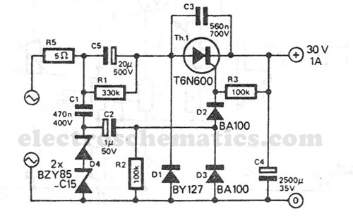
This transformerless power supply circuit is designed for medium current applications. During the negative half period, the capacitor C5 is charged to the peak voltage of the network. The positive half wave will trigger the thyristor, allowing the electric...

Sometimes amateurs like to home-brew their power supplies instead of purchasing one off the shelf at any of the major ham radio retail dealers. The advantage to rolling your own power supply is that it teaches us how they...

This transmitter is basic but allows the transmission of audio to an AM radio. It consists of an RF oscillator operating in the AM broadcast band, along with a modulator stage that mixes the incoming audio with the RF...
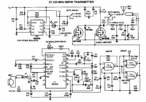
A 27MHz NBFM transmitter circuit schematic featuring the MC2833 and two MPF6660 FET transistors. Utilizing the Motorola MC2833 one-chip FM transmitter along with several supporting components and an MPF6660 RF amplifier, this transmitter can deliver up to 3W into...