
Variable Power Supply 0-24V

Parts List:
- R1: 1kΩ, 0.5W
- R2: 820Ω, 0.5W
- R3: 0.6Ω, 1W
- VR1: 470Ω, linear
- VR2: 10kΩ, linear
- VR3: 10Ω, 1W
- C1: 2200µF, 50V
- C2: 200µF, 50V
- D1: 5A diode bridge
- D2: 2A diode
- D3: 24V, 500mW zener diode
- T1: 2N3055
- T2: SL100
- T3: BC148B
- X1: 24V, 1A secondary transformer
The variable resistors (pots) used for voltage adjustment are 23mm carbon-film linear types, while a 10Ω, 1W wire-wound type is implemented for current limiting. All components can be assembled on a group board, and adequate heatsinks should be installed for both the SL100 and 2N3055 transistors to ensure proper thermal management and reliability during operation.
The design of this power supply circuit emphasizes efficiency and simplicity, making it suitable for various applications where a stable and adjustable power source is required. The use of a zener diode for voltage regulation allows for a steady output, while the inclusion of a diode bridge ensures effective rectification of the AC voltage from the transformer. Capacitors are used for filtering, reducing ripple and enhancing the smoothness of the output voltage. Overall, this circuit is a practical solution for users needing a variable power supply with minimal component requirements.The circuit described here is of an economical smooth variable power supply which offers 0V to 24V. It provides all controls and short circuit protection with acceptable regulation and a ripple free supply and yet uses very few components. The circuit described here is of an economical smooth variable power supply which offers 0V to 24V. I t provides all controls and short circuit protection with acceptable regulation and a ripple free supply and yet uses very few components. The transformer used is a readily available 12V-0-12V, 2A type connected at the end terminals for 24V, 1A output.
After rectification and filtering, a constant reference voltage is obtained by the 24V, 500mW zener diode. PARTS LIST R1 1k © 0. 5W R2 820 © 0. 5W R3 0. 6 © 1W VR1 470 © LIN VR2 10K LIN VR3 10 © 1W C1 2200 µF 50V C2 200 µF 50V D1 5A Diode Bridge D2 2A Diode D3 24V 500mw zener T1 2N 3055 T2 SL 100 T3 BC 148B X1 SEC 24V, 1AMP The pots used for voltage variation are 23mm carbon-film linear type and for current limit 10 ohm, 1w wirewound type is used.
All the components can be connected on a group board. Necessary heatsinks should be provided for both SL100 and 2N3055. 🔗 External reference
Related Circuits
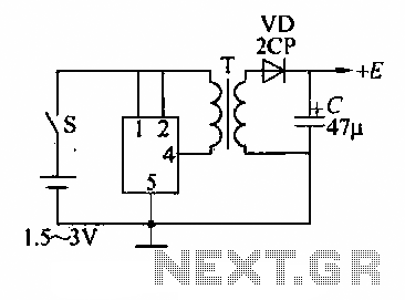
A DC booster circuit is illustrated in the figure, which represents a step-up transformer circuit diagram. The step-up transformer (T) can be utilized to power small transistor radios. The winding ratio can be adjusted to achieve the desired output...
The supply voltage should be about +/- 35 Volts at full load, which will let this little guy provide a maximum of 56 Watts (rated minimum output at 25 degrees C). To enable maximum power, it is important to...
When the weather is hot and the sun is shining, the car fails to start, and the radio, keyless entry, power windows, power locks, and power seats do not function. However, after sunset, everything operates normally. It is important...
This circuit generates three source-regulated voltages using a minimal number of electronic components. The output DC voltages are +12V, +5V, and -5V. Diodes D2 and D3 perform full-wave rectification while charging capacitor C2 during each half of the alternating...
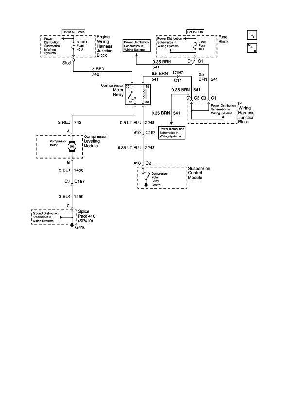
The physical location of the compressor relay is needed, as well as instructions on how to test the pressure sensor on the plastic tank of the compressor assembly. The exact location of the relay has not been confirmed, but...
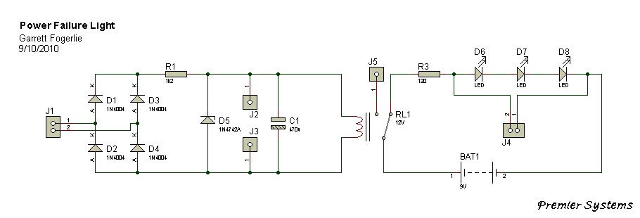
This is a very basic power failure lighting circuit based around a relay. This simple circuit has many uses, from lighting up rooms and walkways in the case of a power failure, to monitoring and security uses. There are...