
Self-control digital inverter power supply circuit diagram:1.2V rising to 9V

The circuit described is designed to operate efficiently without the need for additional components like a power switch, which simplifies the overall design and reduces potential points of failure. The focus on low power consumption is critical for applications where energy efficiency is paramount, such as in portable or battery-operated devices. Stability and reliability are essential attributes that ensure consistent performance over time, making this circuit suitable for precision instruments where accuracy is vital.
The E3-type transformer core is specifically chosen for its properties that enhance performance in this circuit configuration. By cutting and processing the core into a mouth shape, the design likely optimizes magnetic coupling and minimizes losses, which contributes to the overall efficiency of the circuit. The transformer plays a crucial role in voltage transformation and isolation, ensuring that the circuit operates safely and effectively without introducing noise or distortion that could affect measurement accuracy.
Inductor L2, positioned within the circuit, likely serves to filter or smooth out signals, further enhancing the stability of the system. The placement and specifications of L2 would be critical in determining the overall frequency response and transient behavior of the circuit.
In summary, this circuit design emphasizes simplicity and efficiency while maintaining high performance and accuracy. The integration of the E3-type transformer and the strategic use of inductors highlights the thoughtful approach taken in its development, making it a robust solution for various electronic applications.It does not require the establishment of a separate power switch or transformation to switches in the table. The circuit has the advantages of low power consumption, stability and reliability, no effect on instrument accuracy and so on.
The transformer T in the circuit is E3-type core, to cut off each corner and process to be the mouth shape, L2 is inside wh.. 🔗 External reference
Related Circuits
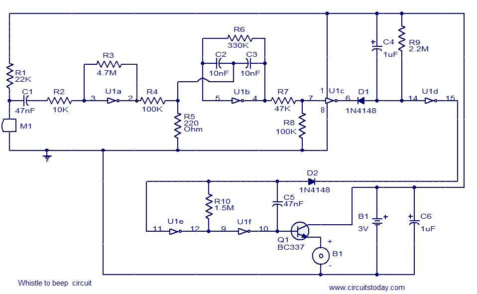
This simple circuit produces a beeping sound that lasts for approximately 3 seconds whenever a whistle is made. The CMOS Hex inverter CD4049 serves as the core component of this circuit. Among the six inverters in the CD4049, U1a...
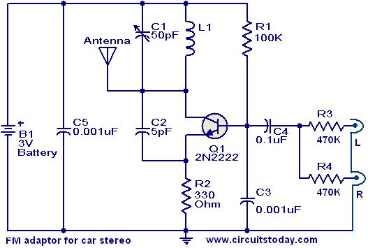
This compact FM adapter circuit, when connected to the audio output of a cassette player or iPod, enables the user to listen to their favorite music through a car stereo. It is particularly useful for vehicles that lack an...
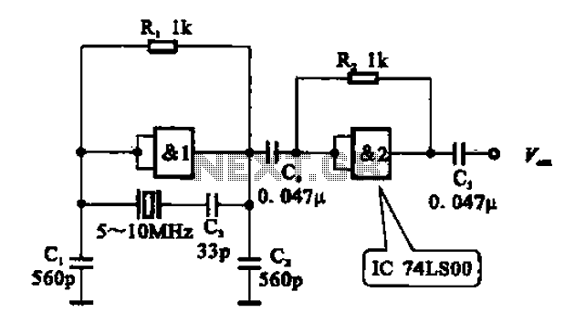
A crystal oscillator circuit comprises various gates as illustrated in the provided figures. Figure (A) represents a crystal oscillator circuit operating at 1 MHz, while figure (B) depicts a 20 MHz crystal oscillator circuit. Figure (C) shows a variable...
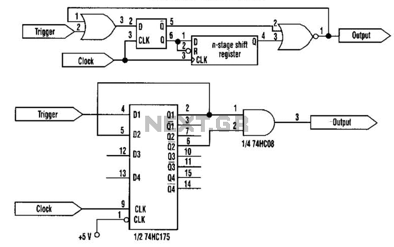
This approach utilizes a Hip-Hop, a shift register, and two gates (A). Before the one-shot pulse, the output of the NOR gate is 0. Consequently, the data input of the D-type flip-flop is equivalent to the trigger. When a...
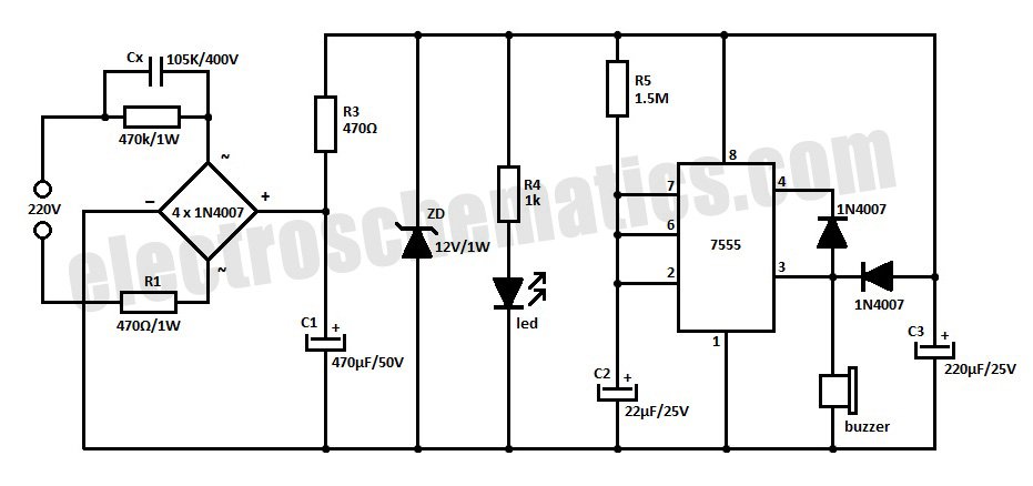
This is a simple power resumption alarm circuit that can be installed within the switch box. It emits beeping sounds when power is restored following a power failure. The power resumption alarm circuit is designed to provide an audible alert...
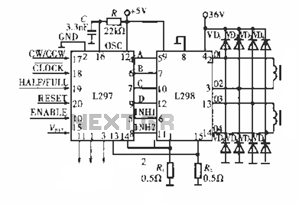
The circuit operates using a dedicated stepping motor controller, the L297. Pin 17 (CW/CCW) is utilized to control the rotation direction of the stepper motor. Pin 18 (CLOCK) regulates the speed of the stepper motor, while pin 19 (HALF/FULL)...