
Soil Moisture Tester Circuit

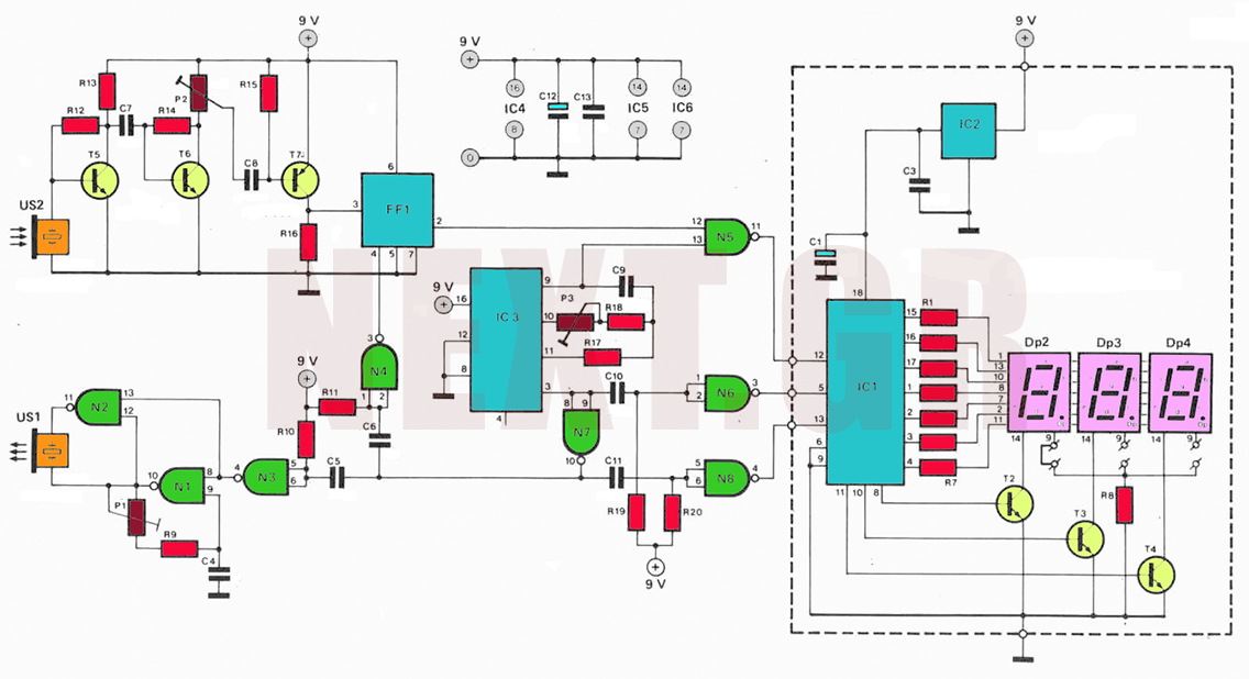
The soil moisture tester is a device designed to measure the moisture content in the soil, providing users with an indication of the hydration needs of their plants. The circuit typically consists of a moisture sensor, a microcontroller, and a display unit.
The moisture sensor is usually a resistive or capacitive type. In a resistive sensor, two metal probes are inserted into the soil. The resistance between these probes changes with the moisture level; as the soil becomes drier, the resistance increases. Conversely, a capacitive sensor measures the dielectric constant of the soil, which varies with moisture content. Capacitive sensors are generally more durable and less prone to corrosion compared to resistive ones.
The microcontroller processes the readings from the moisture sensor. It converts the analog signal from the sensor into a digital value that can be interpreted. This microcontroller can be programmed to set thresholds for moisture levels, allowing it to trigger alerts when the soil is too dry or too wet.
The display unit, which can be an LCD or LED, shows the moisture level in real-time. Some advanced models may include a graphical interface that provides additional information, such as optimal moisture levels for specific plants.
Power for the device can be supplied by batteries or an external power source, depending on the design. To enhance usability, features such as a low battery indicator or a calibration option for different soil types may be included.
Overall, the soil moisture tester is a practical tool for gardeners and plant enthusiasts, enabling them to maintain optimal plant health without the need for direct soil contact.For those of us who don t like to get their hands dirty, this simple soil moisture tester quickly checks the state of their plants and how much attention t.. 🔗 External reference
Related Circuits
The following circuit illustrates the sensor circuit of an analog line follower robot. Features include control by a microcontroller and a sensor circuit. The sensor circuit for an analog line follower robot is designed to detect the presence of a...
The following circuit illustrates a Dancing LEDs electronic circuit diagram. This circuit is based on the LM358 integrated circuit. Features: IC1A amplifies the signal. The Dancing LEDs circuit utilizes the LM358 operational amplifier to create a visually appealing light display....
The circuit utilizes ultrasonic oscillations to measure the distance between two points based on the speed of sound in air. By measuring the time it takes for the ultrasonic wave to travel between these points, the distance can be...
The electronic circuit simulates bird sounds under varying lighting conditions, particularly influenced by neon light irradiation, resulting in fluctuating and changing tones. The sound produced is continuously variable. The schematic of this circuit is provided. The described electronic circuit utilizes...
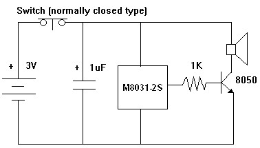
The M8031 circuit features an integrated RC oscillator and digital envelope circuits, which minimize the need for external components. It produces a sound that mimics a mechanical ding-dong. The M8031 operates with a low input voltage range of 1.3...
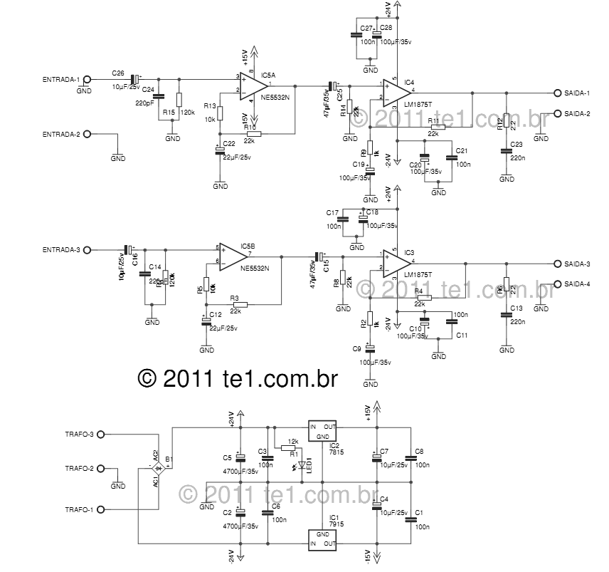
The LM1875 delivers 20 watts into a 4 or 8-ohm load on ±25V supplies. Using an 8-ohm load and ±30V supplies, over 30 watts of power may be delivered. The amplifier is designed to operate with a minimum of...