
Bar-Mode Lights Sequencer

The circuit design involves connecting the terminal of resistor R7, which serves as a selection mechanism, to specific output pins of integrated circuits IC2 and IC3. This connection determines how many LEDs or LED clusters will be activated based on the selected output. When R7 is connected to pin #11 of IC2, it enables the control of seven outputs, effectively allowing the user to drive seven separate LEDs or clusters. The outputs are sequentially numbered, facilitating an organized approach to managing the connected components.
The cluster driver circuits, which can accommodate up to 15 configurations, are structured with two transistors and three resistors for each cluster. This arrangement allows for the effective management of power and signal distribution to the LEDs. The first eight clusters are driven by IC2, while IC3 handles the remaining clusters, thereby extending the capability of the circuit to manage a larger number of outputs.
In cases where only a single LED is required per output, the design can be simplified by substituting the cluster driver with a single transistor. This modification is exemplified in the circuit that includes diode D2, transistor Q3, and resistors R8 and R9. This streamlined approach reduces component count and complexity while still providing the necessary functionality for driving individual LEDs. The overall design is versatile, allowing for both cluster and single LED configurations based on user requirements.The terminal of R7 bearing an arrow must be connected to the desired output pin of IC2 or IC3 in order to select the number of LEDs or clusters forming the bar. For example: if you want to drive seven LEDs or clusters connect R7 to pin#11 of IC2 (Output 8) and the LED or cluster drivers to Outputs 1 to 7 respectively.
Up to 15 of these cluster dri ver circuits, each formed by the LEDs, two transistors and three resistors can be built and connected to the progressively numbered outputs of IC2 (the first eight clusters) and IC3 (the remaining clusters). Wanting to drive only one LED per output instead of a cluster, the above mentioned cluster driver can be substituted by a single transistor, as shown in the circuit formed by D2, Q3, R8 and R9.
🔗 External reference
Related Circuits
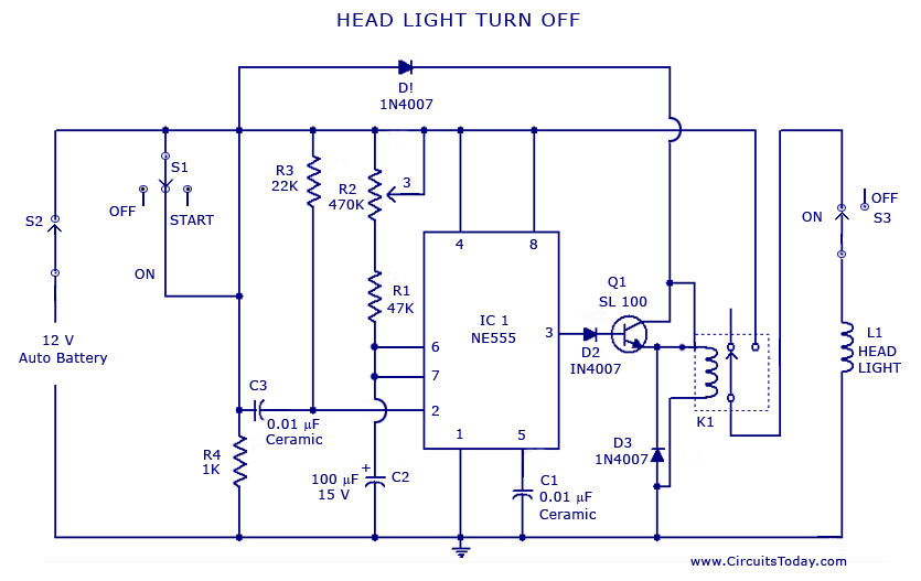
A circuit that can automatically turn off the headlights or lamps of a vehicle after a preset time. This light switching circuit is constructed using a 555 timer integrated circuit (IC). The described circuit utilizes the 555 timer IC in...
The circuit below turns on a light corresponding to the first of several buttons pressed in a "Who's First" game. Three stages are shown but the circuit can be extended to include any number of buttons and lamps. Three...
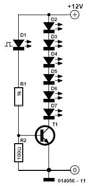
This simple and inexpensive circuit is not limited to Christmas. It consists of two resistors, a small-signal transistor such as a BC547, one flashing LED, and a string of standard LEDs. The flashing LED functions as an oscillator, turning...
Christmas is approaching, and it is the time of year when electronics students and hobbyists consider creating a Christmas circuit for their homes, particularly one that features flashing lights. Numerous circuits and kits are available that can flash various...

The following circuit illustrates the sensor circuit diagram for automatic room lights. This circuit is based on the CD4017 integrated circuit (IC) and features the use of two light-dependent resistors (LDRs). The automatic room light circuit utilizes the CD4017 decade...
This device is a simple timer that allows the headlights of a vehicle to remain on for approximately 1 minute and 30 seconds. This feature is useful when accessing dark areas without the need to return to turn off...