
Baseband Circuits for an RFID Receiver

The described circuit comprises a direct conversion RF receiver, which efficiently demodulates radio frequency (RF) signals directly to baseband without intermediate frequency stages. This is achieved using the LT5516 direct conversion demodulator, which operates within a frequency range of 800 MHz to 1.5 GHz, making it suitable for applications such as RFID systems. The receiver's architecture utilizes a shared antenna for both transmission and reception, which facilitates the detection of RF signals.
Upon receiving the RF carrier, the signal is processed through a bandpass filter and fed into the LT5516, which is known for its high linearity, allowing it to maintain sensitivity even amidst significant interference. The output from the LT5516, which is in a differential format, is then converted to a single-ended signal by the LT6231 low noise dual operational amplifier. This conversion is essential for interfacing with subsequent circuit stages, particularly the lowpass filter.
The LT1568 is employed for analog baseband filtering, capable of implementing lowpass and bandpass filtering with customizable cutoff frequencies from 100 kHz to 10 MHz. This is particularly relevant for handling the typical signal spectrum in UHF RFID applications. The differential output from the LT1568 drives the LTC2298, a dual 14-bit ADC capable of sampling at 65 Msps with a commendable signal-to-noise ratio of 74 dB, ensuring high fidelity in digital signal conversion.
To mitigate high-frequency noise, external capacitors are utilized across the resistors in the LT6231, limiting the output frequency to 10 MHz. The circuit employs AC coupling to the baseband amplifier, as DC coupling is unnecessary for the amplitude shift keying (ASK) modulation used in RFID signals. The design incorporates highpass filtering characteristics, with a cutoff frequency set at 8 kHz to optimize performance.
Furthermore, the LT1568 is configured in a dual arrangement to create matched fourth-order filters for I and Q signal processing, ensuring consistent performance across both channels. The filter design achieves a stopband attenuation of 34 dB at double the –3 dB frequency, and the inherent matching of the LT1568 components guarantees that both I and Q filters maintain similar characteristics, which is crucial for accurate signal demodulation. The LTC2298 ADC's input voltage range can be adjusted, accommodating different signal levels and ensuring compatibility with the overall system design.Figure 1 shows the block diagram of a direct conversion RF receiver—the receiver demodulates an RF carrier directly into a baseband signal without an intermediate frequency down-conversion (a zero IF receiver). The antenna, shared by both the transmitter and receiver, detects an RF carrier and passes it through a bandpass fi lter to an LT®5516 demodulator’s RF input.
The LT5516 direct conversion demodulator frequency range of 800MHz to 1.5GHz includes the UHF range used by RFID readers (860MHz to 960MHz). The excellent linearity of the LT5516 provides for high sensitivity to low level signals, even in the presence of large interfering signals.
The LT6231 low noise dual op amp acts as a differential to single-ended amplifi er to drive the single-ended input of the lowpass fi lter.
Analog baseband fi ltering is performed by the LT1568, a low noise, precision RC fi lter building block. The LT1568 fi lter provides a simple solution for designing lowpass and bandpass fi lters with cutoff frequencies from 100kHz to 10MHz.
These cutoff frequencies are suffi cient for the 250kHz to 4MHz signal spectrum typically used in UHF RFID systems. The differential output of an LT1568 drives the inputs of an LTC2298 ADC. The LTC2298 is a 65Msps, low power (400mW), dual 14-bit analog to digital converter with 74dB signal-to-noise ratio (SNR).
The digital signal processor (DSP) that follows the ADC analyzes the received signal from multiple tags and provides additional fi ltering. A Low Noise Differential to Single-Ended Amplifi er Figure 2 shows an LT6231 difference amplifi er used to convert the LT5516 differential I or Q output to a singleended output.
The addition of external 270pF capacitors across the 60Ω resistors limits the demodulator’s output to 10MHz to prevent any high frequency interference from reaching the LT6231 amplifi er. AC coupling to the baseband amplifi er is used because DC coupling is not necessary for the amplitude shift keying (ASK) RFID signal.
The highpass pole provided by the AC coupling capacitors and the amplifi er input resistors is set to 8kHz. The differential amplifi er’s input resistors are set to 140Ω in order to minimize the input referred noise.
The noise fl oor at the amplifi er’s output is 4.3nV/√Hz times the amplifi er gain (gain ≥ 5). The 1.5V reference provided by the LTC2298 ADC is used to level shift the amplifi er’s output to the mid-supply point of the following 3V fi lter and ADC circuits.
A Matched I and Q Filter and a Dual ADC Figure 3 shows two LT1568 fi lter building blocks connected as dual, matched, fourth order fi lters. The LT1568 fi lter’s single-ended input to differential output conversion gain is 6dB. The LT1568 circuit implements an elliptic lowpass fi lter function with equal resistor values (see Figure 3).
Stopband attenuation at 2(f–3dB) is 34dB. I and Q fi lter matching is assured by the inherent matching of the LT1568s’ A and B sides. The input voltage range of an LTC2298 is adjustable to 2VP-P or 1VP-P
Related Circuits
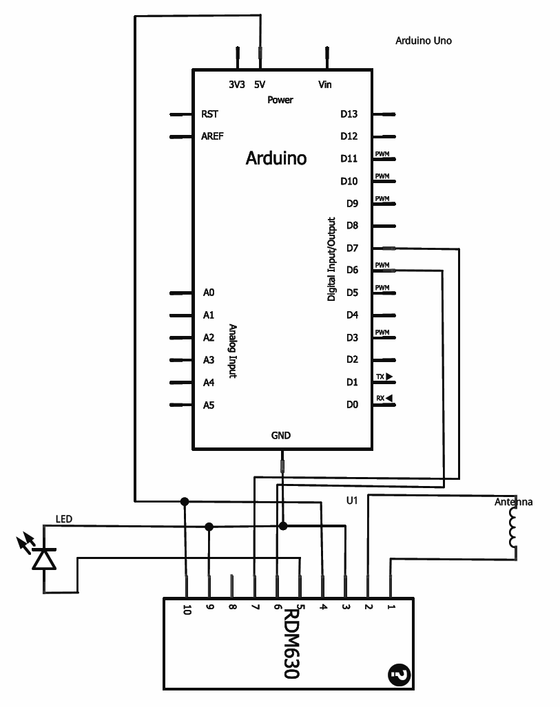
This tutorial provides guidance on integrating RFID functionality into a project using the RDM630 module from Seeed Studio, specifically its UART version. The module is mounted on a compact board with pre-soldered connectors, making it compatible with breadboards. To...
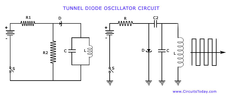
The operation of Negative Resistance Oscillators, including types such as Dynatron and Tunnel Diode Oscillator, along with their characteristics and circuit diagrams, is explained. Negative resistance oscillators are electronic circuits that exploit the phenomenon of negative resistance to generate oscillations....
How to build your own RFID system using a microcontroller. This schematic is very simple. Building a Radio Frequency Identification (RFID) system using a microcontroller involves several key components and a straightforward schematic design. The essential elements of an RFID...
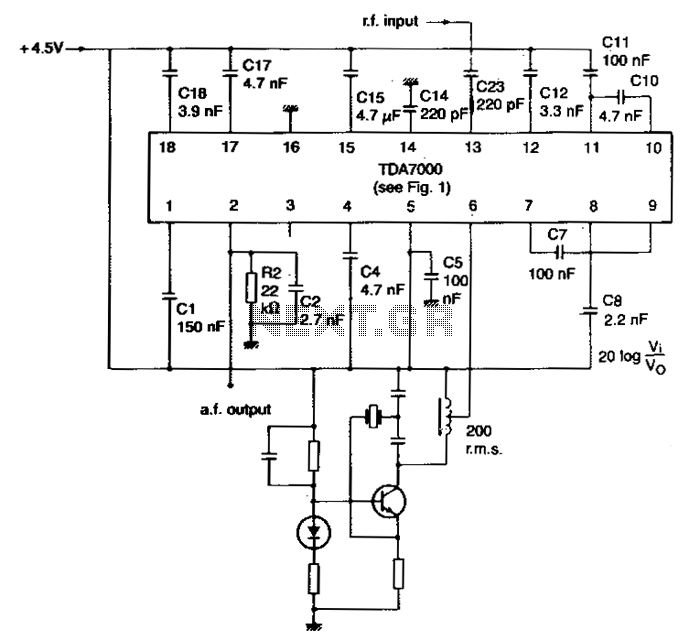
The local oscillator is controlled by a crystal, and the intermediate frequency (i-f) swing is minimally compressed. To prevent significant distortion of the demodulated audio signal, the deviation of the transmitted carrier frequency due to modulation must be limited....
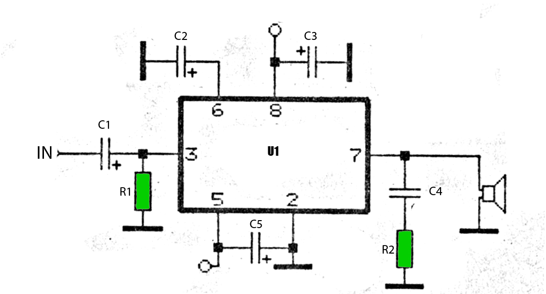
The car power amplifier utilizes the SI1050GL integrated circuit (IC) as the primary amplification component. It delivers an output power of 50 Watts at an 8-ohm mono impedance. The amplifier operates with a DC voltage of up to 25...
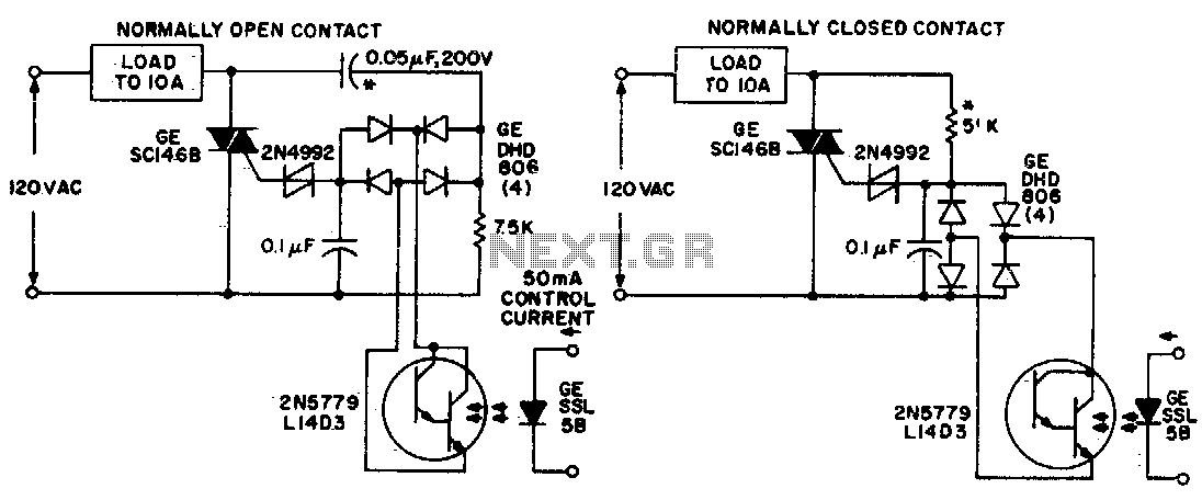
Both circuits utilize the GE SC146B, a 200 V, 10 A Triac for load current contacts. These triacs are activated by standard SBS (2N4992) trigger circuits, which are managed by a photo-Darlington configuration, functioning through the DA806 bridge as...