
automatic street light control system

The automatic street light system circuit utilizes an LDR as the primary sensor to detect ambient light levels. The LDR is configured in a voltage divider arrangement with a fixed resistor (56KΩ) to create a varying voltage signal based on the light intensity. When light levels are high, the resistance of the LDR decreases, resulting in a lower voltage drop across it. Conversely, in darkness, the resistance increases, leading to a higher voltage drop. This voltage is fed to the base of a BC 187 transistor, which acts as a switch for the street light.
When the ambient light level drops below a certain threshold, the voltage at the base of the transistor reaches a level sufficient to turn it on, allowing current to flow through the collector-emitter path. This, in turn, powers the incandescent lamp connected to the circuit. The system is designed to minimize energy consumption by ensuring that the street lights are only activated when necessary.
For improved efficiency, solar-powered LED systems can be integrated into this design. In such systems, solar panels charge batteries during the day, providing power for the LEDs at night. This not only enhances energy savings but also promotes sustainability. The use of an LDR in this context ensures that the lights operate only when required, further optimizing energy use.
In summary, this automatic street light system effectively demonstrates the application of an LDR in controlling street lighting through a simple yet effective electronic circuit, showcasing an energy-efficient solution for urban lighting needs.Automatic Street light system is very common nowadays as it provides intelligent street lighting mechanism. It provides light automatically during night. These energy saving street lights make uses of incandescent lamps instead of LEDs. So here we will teach you how to make an electronic circuit for street light automation. The heart of this circuit is a LDR (Light Depended Resistor) which is connected as a potential divider with a 56K resistor. The drop across LDR is used for switching the transistor. Solar led street lighting systems are the advanced versions of this ordinary automatic street light controller. The unique property of LDR (Light Depended Resistor) is utilized here. LDR is a variable resistor. It has very low resistance in the presence of light and very high resistance in the absence of light.
Here the drop across LDR varies with changes in light intensity. That is voltage drop across the LDR is minimum in the presence of light and maximum in the absence of light. One end of the LDR is connected to the base of a BC 187 transistor. At night, the drop is very high (> 0. 6V) and it is sufficient to turn on the transistor. 🔗 External reference
Related Circuits

LM35 IC Thermal Control Circuit Diagram. Features: The LM35DZ detects when the temperature exceeds a preset level and can be utilized in various applications. The LM35 IC thermal control circuit is designed to monitor temperature and provide a corresponding output...
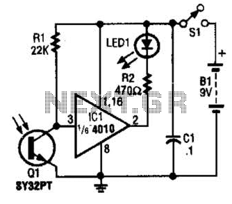
The IR Tester circuit indicates whether the button pressed on a remote control is functioning. Q1 is a phototransistor that is activated by infrared (IR) energy. The IR Tester circuit operates by detecting infrared signals emitted by remote control devices...
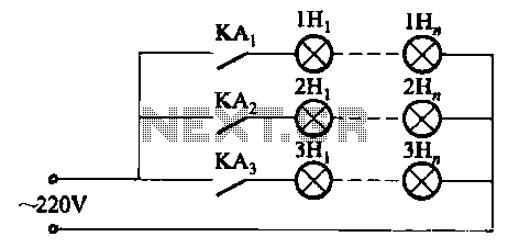
The relay control system utilizes multiple pairs of contacts, allowing for the connection of higher power lamps in parallel. The circuit design is straightforward; by altering the capacitance of the capacitor, different flashing frequencies can be achieved. The described circuit...
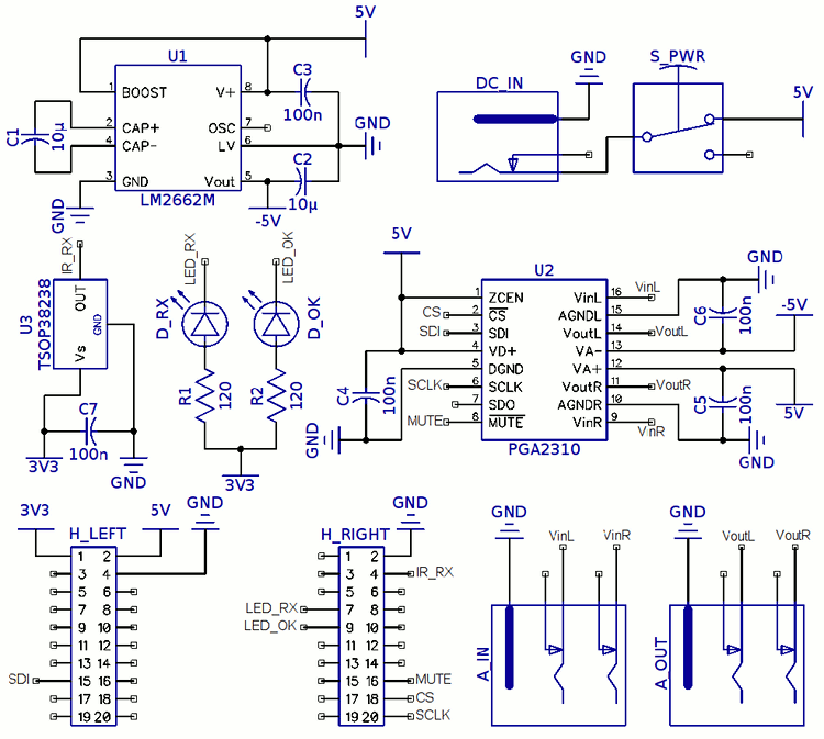
The television screen used at home features built-in speakers; however, since it functions as a computer display, it lacks an infrared receiver. This limitation prevents volume adjustment using the TV receiver remote. A recent acquisition of Stellaris LaunchPad development...
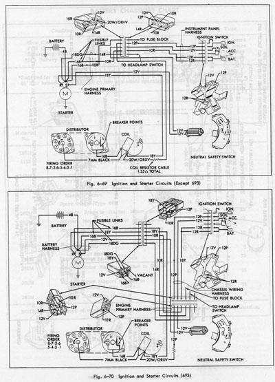
The system operates solely on vacuum. Upon inspection of the vacuum hoses, two brittle hoses were found that ran through the firewall to the headlight switch, where a slight hissing sound was noticeable when the lights were activated. Touching...
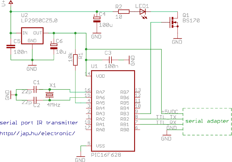
This is a programmable infrared (remote control) transmitter, which can be controlled from a PC serial port. It is capable of sending many remote control formats, including the Philips RC-5 standard. Exact formats with the timing parameter names are...