
Furnace Fuel Miser Circuit

The schematic design incorporates an LM555 timer configured in astable mode to generate a pulse-width modulation (PWM) signal that adjusts the duty cycle. This PWM signal is then fed into a decode counter (V2), which can be programmed to output specific duty cycles, allowing precise control over the heating duration. The output from V2 is linked to a latch circuit formed by V3A and another component, which ensures that the control signals for the heating system components, including Al and LED1, are stable and reliable.
The triac (TRI) is employed as a switching device to control the AC supply to the heating system. When the triac is triggered, it allows current to flow through the heating element, effectively controlling the heating process. The integration of a heavy-duty relay (K1) is crucial for systems that require higher current handling, ensuring that the relay can manage the load without failure.
In scenarios where oil-fired heating systems are used, the schematic accounts for the inclusion of a three-wire thermostat. This thermostat is responsible for managing the burner motor and ignition system, activating a relay to facilitate operation. This relay acts as a safety and control mechanism, ensuring that the heating system operates efficiently and safely.
Overall, the described circuit effectively combines timing, control, and high-current switching elements to create a robust heating control system. The design ensures flexibility in duty cycle adjustments while maintaining safety and reliability in operation. A timer (LM555CN) and decode counter is used to generate duty cycles from 10% to 100% to control the time a heating system can operate. V2 is a decode counter that can be switched from 10% to 100% duty cycle. V3A and form a latch that drive Al, LED1, and V4. The triac TRI is used as an ac switch, in series with the thermostat that controls the heating system.
Electric-heating systems thai do nut contain a low-current thermostat (as in the previous installation), use a heavy-duty thermostat that directly feeds current to the heating element.For such systems, it will be necessary to install a heavy-duty relay (Kl in this example) to control the heavy heating-element current. Some oil-fired systems use three-wire thermostats to control the operation of the burner motor and ignition system by activating a relay. This is a typical installation for such systems.
Related Circuits
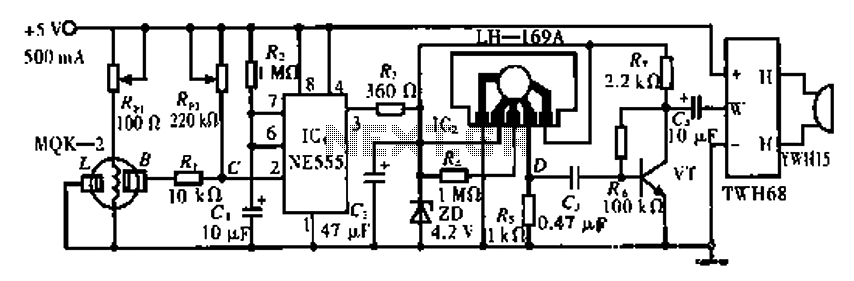
The circuit operates using the MQK-2 gas sensor, which detects the presence of combustible gases or smoke through surface adsorption. When gas is detected, the inter-electrode resistance (BL) decreases significantly. This change in resistance affects the voltage at node...
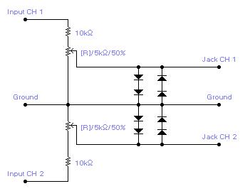
For simple electronic circuits, it may be sufficient to gain qualitative insights on dedicated electrical signals. This interface circuitry allows the line-in input of a standard PC sound card to be utilized as a 2-channel oscilloscope. Although this setup...
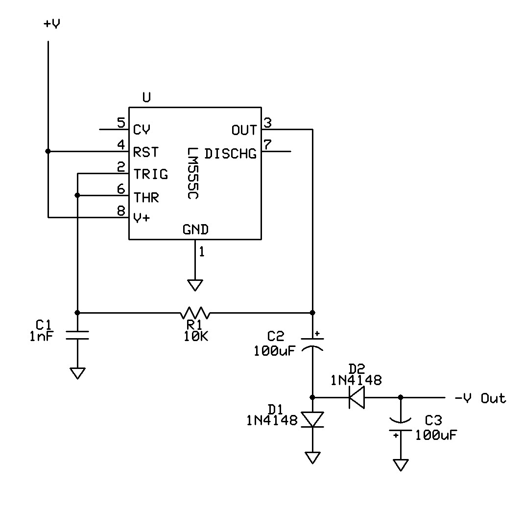
Can a 555 negative supply circuit, like the one below I pulled from another schematic, supply enough negative voltage to an LM324 and an AD736JN? The 555 timer integrated circuit can be configured to generate a negative voltage supply,...
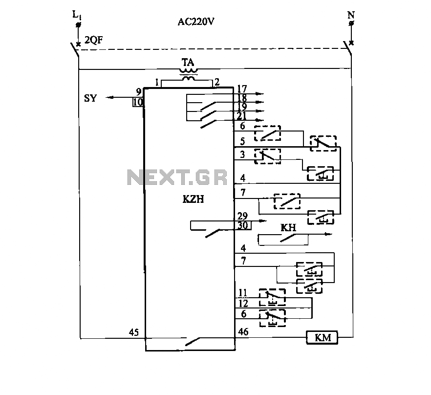
It utilizes the SHD series of electronic control equipment modules. The fan control box KZH functions as the HKD 1F electronic module. The SHD series of electronic control equipment is designed for various applications, including fan control systems. Within this...
This general-purpose amplifier has a bandwidth of approximately 20 MHz and it uses an LM733/NE592 video amplifier integrated circuit. This circuit can be utilized as a line driver or as a LAN line driver. The circuit employs the LM733/NE592 video...
This project flashes eight LEDs in an apparently random manner. It uses a 4060 combined counter and display driver IC which is designed for driving 7-segment LED displays. The sequence is not really random because seven of the LEDs...