
Basic mosfet switch question

The schematic in question involves a MOSFET switch designed to control the power supply to a light source, with the aim of minimizing battery drain when the light is not active. The MOSFET is utilized for its high efficiency and low on-resistance, which allows for effective switching with minimal power loss.
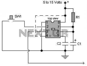
In the proposed circuit, the microswitch serves as the control mechanism for the MOSFET gate. When the microswitch is activated, it applies a voltage to the gate of the MOSFET, allowing current to flow from the source to the drain, thereby powering the light. When the microswitch is released, the gate voltage drops, turning off the MOSFET and effectively cutting off power to the light. This configuration ensures that the light is only powered when needed, significantly reducing the risk of battery drainage during periods of inactivity.
It is essential to consider the MOSFET's specifications, including its threshold voltage and maximum current rating, to ensure compatibility with the light source and the power supply. Additionally, incorporating a pull-down resistor at the gate can help ensure that the MOSFET remains off when the microswitch is not engaged, preventing any unintended power leakage.
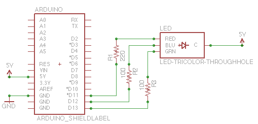
Overall, this circuit design enhances the efficiency of the light system while maintaining a compact form factor, making it suitable for applications where space is limited and battery life is critical.In this schematic, provided by Jimmy M, would this circuit drain the batteries when the light is not in use? I`m considering building a mosfet circuit like this to use in a compact M@g where I discard the original bulky switch and use a microswitch to operate the mosfet..
🔗 External reference
Related Circuits
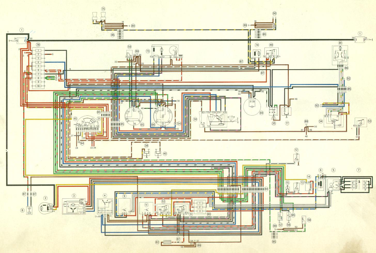
The objective is to investigate low RPM issues and gather expert opinions before proceeding with the disassembly of wire looms for tracing purposes. To address low RPM problems in an electronic system, it is essential to conduct a thorough analysis...
This is a lamp timer capable of operating two separate relay switches. Outputs can be in three (or restricted to two) states: OFF, delayed ON and constant ON. Delayed ON mode is indicated by the LEDs. The source code...
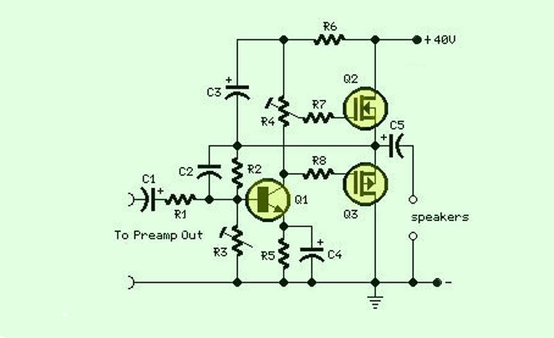
The function of this circuit is an audio amplifier capable of delivering a decent output power with a minimal number of components, with considerable efficiency. This audio amplifier circuit is designed to enhance audio signals, providing sufficient output power while...
The capability to control lights and fans wirelessly has transitioned from an expensive luxury to widely accessible consumer solutions. Nevertheless, creating a custom solution remains an engaging project for hobbyists and tinkerers. RobotGrrl has developed user-friendly libraries aimed at...
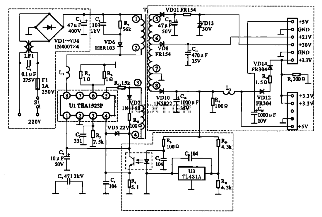
The East Shi IDS-2000F STB switching power supply circuit primarily consists of an AC input circuit, a switching oscillation circuit, an output circuit, and a secondary steady voltage control circuit. The AC input circuit includes a switch (S), fuse...
A multivibrator is an electronic circuit used to implement a variety of simple two-state systems such as light-emitting diodes, timers, and flip-flops. The monostable multivibrator will create a condition in which one of the states is stable. A multivibrator circuit...