
Transistorized flashers

Performance has been verified at ambient temperatures of -40°F, 77°F, and 212°F. A GE 5-volt, 90-milliampere type No. 1850 lamp is utilized.
The circuit operates based on the interaction between transistors Q1 and Q2, which are configured to form a multivibrator. In this arrangement, Q1 and Q2 alternately switch on and off, generating a square wave output at the emitter of Q2. This output signal is then used to drive the base of transistor Q3, which functions as a common emitter amplifier. The amplified output from Q3 is responsible for controlling the lamp, enabling it to turn on and off at the desired flash rate.
The timing characteristics of the multivibrator circuit are determined by the values of the resistors R2 and R3, and capacitors C2 and C1, respectively. The flash duration is influenced by the time constant created by R2 and C2, while the off interval between flashes is determined by the time constant of R3 and C1. This design allows for flexibility in adjusting the timing parameters independently, catering to various application requirements.
It is essential to maintain tight tolerances for R2, R3, C1, and C2, especially in applications where precise timing is critical. Variations in these component values can lead to inconsistent flash rates, which may not be acceptable in safety-related applications such as barricade warning flasher lights.
The circuit has been tested for reliable performance across a wide temperature range, ensuring functionality in extreme environmental conditions. The use of a GE 5-volt, 90-milliampere type No. 1850 lamp provides a standard illumination source, suitable for the intended application in highway construction zones. This lamp specification ensures adequate visibility while operating under various ambient conditions, contributing to the effectiveness of the warning system.Transistors Ql and Q2 are connected as a free running multivibrator. The output, at the emitter of Q2, drives the base of the common emitter amplifier Q3, which controls the lamp. This circuit configuration permits the flash duration, the interval between flashes, and the lamp type to be varied independently.
Flash duration is proportional to the product of R2C2 while the off interval is proportional to the product of R3C1. Consequently, when the flash timing must be accurately maintained, these component tolerances will have to be held to similar limits.
All three circuits described are designed for barricade warning flasher lights such as used in highway construction. They differ only in flash duration which normally is 15%, 25%, or 50% of the flash rate. Performance has been checked at ambient temperatures of -40°F, 77°F, and 212°F. A GE 5 volt, 90 milliampere type No. 1850 lamp is used.
Related Circuits

Each bistable circuit comprises two oppositely-symmetrical germanium transistors, two diodes, and four resistors. An additional transistor, Q, facilitates the transition of the conducting state to the next position when actuated by a transfer pulse. The absence of capacitors allows...
The schematic illustrates a standard AM radio circuit utilizing NPN transistors. This generic circuit does not provide specific values for all components, serving instead as a reference point for experimenters to begin their projects. The schematic of a typical transistor...
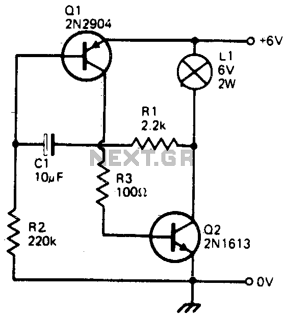
This simple circuit will flash a 6-volt lamp at a rate determined by the size of capacitor C1. It is most economical on power as it only draws current when the lamp is on. When the lamp is off,...

A schematic of a typical transistor AM radio is presented. This circuit utilizes npn transistors. It is a generic circuit; hence, specific values for some components are not provided. This circuit serves as a reference point for experimenters. The schematic...
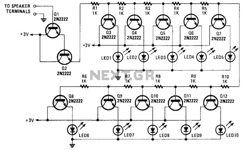
A resistor network (R1 through R10) with emitter followers (Q1 and Q2) drives LED drivers (Q3 through Q7). This circuit was utilized as a "light organ" to provide visual volume indication. It can be connected to a speaker, another...
More: A comprehensive electronic schematic typically includes various components such as resistors, capacitors, diodes, transistors, and integrated circuits, interconnected to perform specific functions. Each component is represented by standardized symbols, and their values are indicated alongside or...