
Battery Backup for SRAM or Microcontroller

This circuit design incorporates essential elements for ensuring reliable operation during power interruptions. The use of 1N4148 diodes is critical for maintaining unidirectional current flow, which protects the battery from discharging back into the power source. The inclusion of resistor R13 not only limits the charging current but also enhances the safety of the battery charging process.
The design allows for effective management of power states in the microcontroller or processor. By placing the chip in a low-power mode during outages, unnecessary power consumption is minimized. The requirement for high impedance outputs during power failure is crucial, as it prevents inadvertent current draw that could deplete the backup power source.
For applications requiring short-term data retention, the use of a large capacitance capacitor, such as the 4700µF option, can serve as a temporary power source. However, this solution comes with a trade-off in terms of PCB real estate, as larger capacitors occupy more space. For applications necessitating extended backup times, a battery with a sufficient AH rating is essential to ensure that the system remains operational for the desired duration.
Monitoring Vbat and Vcc levels using a comparator like the LM339 allows for proactive management of the power supply. This feature is vital for generating alerts regarding low battery conditions and ensuring that the system can respond appropriately to voltage drops.
The potential for data corruption during power fluctuations emphasizes the need for robust data management strategies. Utilizing flash memory for data storage provides a reliable method for retaining critical information, while SRAM is better suited for applications with high read/write frequency due to its faster access times.
Incorporating a watchdog timer can enhance system reliability by monitoring CPU activity. This feature ensures that the system can recover from non-responsive states, thereby maintaining overall operational integrity. The traditional method of monitoring CPU activity through I/O port scanning remains a viable strategy for detecting system malfunctions.
Overall, this circuit design addresses various challenges associated with power management in microcontroller and SRAM applications, providing a comprehensive solution for ensuring data integrity and system reliability during power interruptions.This circuit can be used as a low cost SRAM and Microcontroller-Microprocessor Battery Backup. All the diodes are 1N4148, The diodes prevent battery discharge back to power source. D8 gives a one way path to charge Battery thru R13 which limits current. D4 ensures a one way path of supply to chip when power is present. D5 is backup supply on power failure. The chip a real time clock, RAM or Processor can be put to standby or sleep on power failure. If it is not a smart chip then make sure on power failure all outputs of chip are high impedance or floating. do not use any pullups or resistor dividers to Vbat, which is the supply to chip. There should be no leakage path from Vbat, decoupling cap of chip must be plastic. If you want to use this circuit for short term retention or for CMOS logic chips then you can use a 4700uF Cap in place of battery.
This works for many hours but the cap has big footprint on PCB. For long duration use more battery AH Ampere-Hour. Vcc is 5V DC regulated. The Vbat and Vcc can be monitored with comparator like LM339, this circuit can generate the reset or low battery signals. The power on reset and power down reset can corrupt data on brown outs or black outs or even spikes and EMI.
So back up data on flash. For Rapid writing and reading SRAM is better and if write-read cycles are high SRAM is best. But if you need to store values and refer to them like a look-up table flash is better. The power fluctuations can hang the chip, so a watchdog chip may be required. The conventional way was the to monitor the keyboard-display scan on a i/o port. If the pulses are coming at the rate you programmed the cpu is alive and kicking and doing its job. If the CPU is Playing Hookey, then the pulses stop coming and it has to be reset. We aim to transmit more information by carrying articles. Please send us an E-mail to wanghuali@hqew. net within 15 days if we are involved in the problems of article content, copyright or other problems. We will delete it soon. 🔗 External reference
Related Circuits
The following circuit illustrates a portable NiCd battery charger circuit diagram. The portable battery charger is designed to facilitate the charging of nickel-cadmium batteries. The portable NiCd battery charger circuit typically consists of several key components, including a transformer, rectifier,...
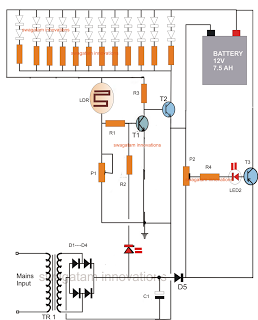
The following circuit is an LED emergency light circuit featuring advanced functionalities such as overcharge battery cut-off, daytime auto-disable, and automatic activation of the LEDs during AC mains failure, reverting to charging mode when power is restored. The circuit...
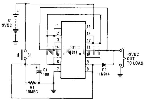
This battery saver circuit can automatically turn off a small piece of test equipment after a desired period of time, allowing for worry-free operation in a workshop environment. The circuit utilizes a CD4011 integrated circuit (IC) to function as...

When USB power is present and the device needs to operate, VSupply is supplied directly by the USB, while a PMOS transistor isolates the battery from the supply. Resistor R3 ensures that the PMOS remains on when USB power...
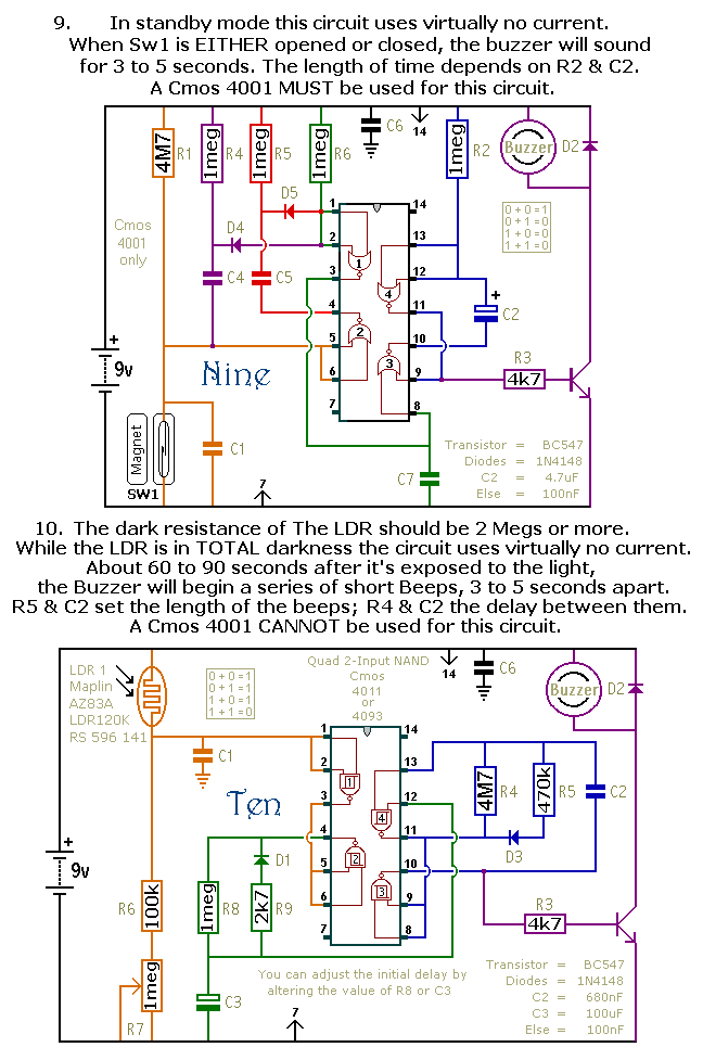
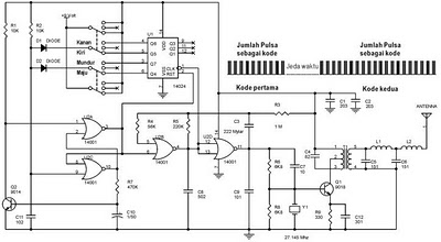
This document outlines a selection of small self-contained alarm circuits. Each alarm's main features are detailed on the circuit diagram. They are designed to have a very low standby current, making them suitable for battery operation. Each pair of...
H-Bridge circuit utilizing transistors for the bidirectional control of a DC motor. Integrated circuits (ICs) containing H-Bridges are employed to simplify the drive circuit. The L293D is a dual H-Bridge motor driver, allowing for the control of two DC...