
Battery charger and PSU

The circuit designed for charging and powering digital cameras incorporates two main components: a charger and an adapter. The adapter utilizes a transformer to step down the mains voltage, which is then rectified by a bridge rectifier to convert the AC to DC. A buffer capacitor smooths out the rectified voltage to provide a stable DC output. The adjustable voltage regulator LM317 is employed to provide a variable output voltage suitable for the camera, adjustable within the range of 2 to 9 volts, depending on the specific requirements of the camera model being used.
In the charger section, a 7805 fixed voltage regulator functions as a current generator, ensuring a constant current flow during the battery charging process. The charging current can be finely tuned using a 100-ohm, 1-watt potentiometer, allowing for adjustments between 50 mA and 300 mA. This is crucial for accommodating different battery types and their specific charging requirements. A small current measuring instrument is included in the circuit to provide real-time feedback on the charging current, enhancing usability.
The design allows for the simultaneous charging of one to four NiMH batteries. A switch is incorporated to select the number of batteries being charged, which is essential to ensure the charging current is appropriately adjusted in accordance with the specifications provided by the battery manufacturer. Notably, the circuit does not include a mechanism for monitoring the charging time or the condition of the batteries. Instead, the manufacturer-recommended charging time, typically ranging from 14 to 16 hours, is adhered to. To address the lack of a built-in timer, a mechanical mains timer is integrated into the system, allowing for automated control of the charging duration while remaining cost-effective and straightforward in design. This approach provides a practical solution for users needing to charge batteries for digital cameras efficiently.This circuit was created for digital cameras. It's known the digital cameras have considerable power consumption. For example my camera Minolta E223 requires approximately 800 mA. In practice a mains power supply or high capacity NiMH accumulators (batteries) can satisfy this demand. This circuit consists of two parts, charger and adapter. The transformer, rectifier bridge and buffer condensator are common. Adapter is quite simply its main part is an adjustable voltage regulator LM 317 according to usual setting.
Output is a suitable for camera jack plug. Voltage can be adjusted in range 2-9 V. In the charger circuit a 7805 fixed voltage regulator works as current generator assured constant current during charging. This charging current can be adjusted with the 100 /1W potentiometer in range about 50-300 mA indicated by a small current measuring instrument.
From one to four batteries can be charged simultaneously. The switch must be set according to number of batteries, and charging current of batteries given by manufacturer must be adjusted. This circuit doesn't measure charging time and charging condition of batteries. Manufacturers give charging time, usually 14-16 h. I solved this problem with a simply, cheap mechanical mains timer. I think its accuracy is sufficient. 🔗 External reference
Related Circuits
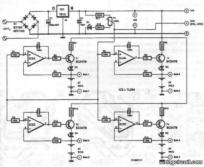
This electronic circuit diagram facilitates the design of a straightforward charging circuit for NiCd batteries. The charger is capable of simultaneously charging four 9V NiCd batteries, with the voltage being adjustable via a potentiometer labeled P1. The described circuit operates...
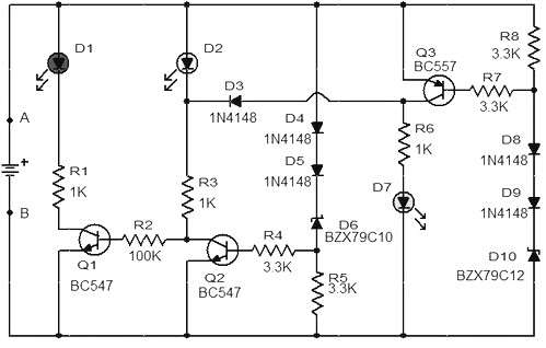
When the battery voltage is 11.5V or less, transistor Q1 is activated, and LED D1 will illuminate. When the battery voltage is between 11.5V and 13.5V, transistor Q2 is activated, causing LED D2 to light up. At a battery...
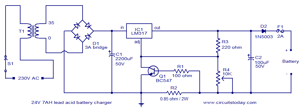
This lead-acid battery charger circuit is designed based on a request from Mr. Devdas C. His requirement was for a circuit that could charge two 12V/7AH lead-acid batteries connected in series. He did not specify the number of cells...
Most Bulle clocks require their magnets to be rejuvenated before they can operate correctly with a standard 1.5V cell. The first significant magnet material was cobalt-chrome steel, introduced in 1921. Prior to this, carbon steel was hardened through heating...
In the circuit below, a quad voltage comparator (LM339) is used as a simple bar graph meter to indicate the charge condition of a 12 volt, lead acid battery. A 5 volt reference voltage is connected to each of...
The above pictured schematic diagram is just a standard constant current model with a added current limiter, consisting of Q1, R1, and R4. The moment too much current is flowing biases Q1 and drops the output voltage. The output...