
Bike Battery Charger

The circuit employs a voltage multiplier configuration, which is essential for stepping up the voltage produced by the bike generator to a level suitable for charging a 12V battery pack. Typically, a bike generator produces an AC voltage that may not be sufficient to charge the battery directly. The voltage multiplier utilizes capacitors and diodes arranged in a specific topology to convert the lower AC voltage into a higher DC voltage.
In this setup, the bike generator's output is first rectified using a diode bridge, which converts the AC output into pulsating DC. Following rectification, the voltage multiplier circuit, composed of multiple stages of capacitors and diodes, is employed to increase the voltage level. Each stage of the multiplier adds to the total output voltage, allowing the circuit to achieve the necessary voltage to charge the 12V battery effectively.
It is crucial to select the appropriate values for the capacitors and diodes to ensure efficient operation and minimize losses. The capacitors should be rated for a voltage higher than the maximum expected output, while the diodes must have a low forward voltage drop to maximize the efficiency of the conversion process. Additionally, the circuit may include filtering capacitors at the output to smooth the DC voltage, providing a more stable charging current to the battery.
Overall, this circuit design is an effective solution for harnessing the energy generated by a bike generator to charge a 12V battery pack, making it suitable for applications where renewable energy sources are utilized.This simple circuit allows a 12V battery pack to be charged via a bike generator. The generator is rated at 3W and with this voltage multiplier circuit pr.. 🔗 External reference
Related Circuits
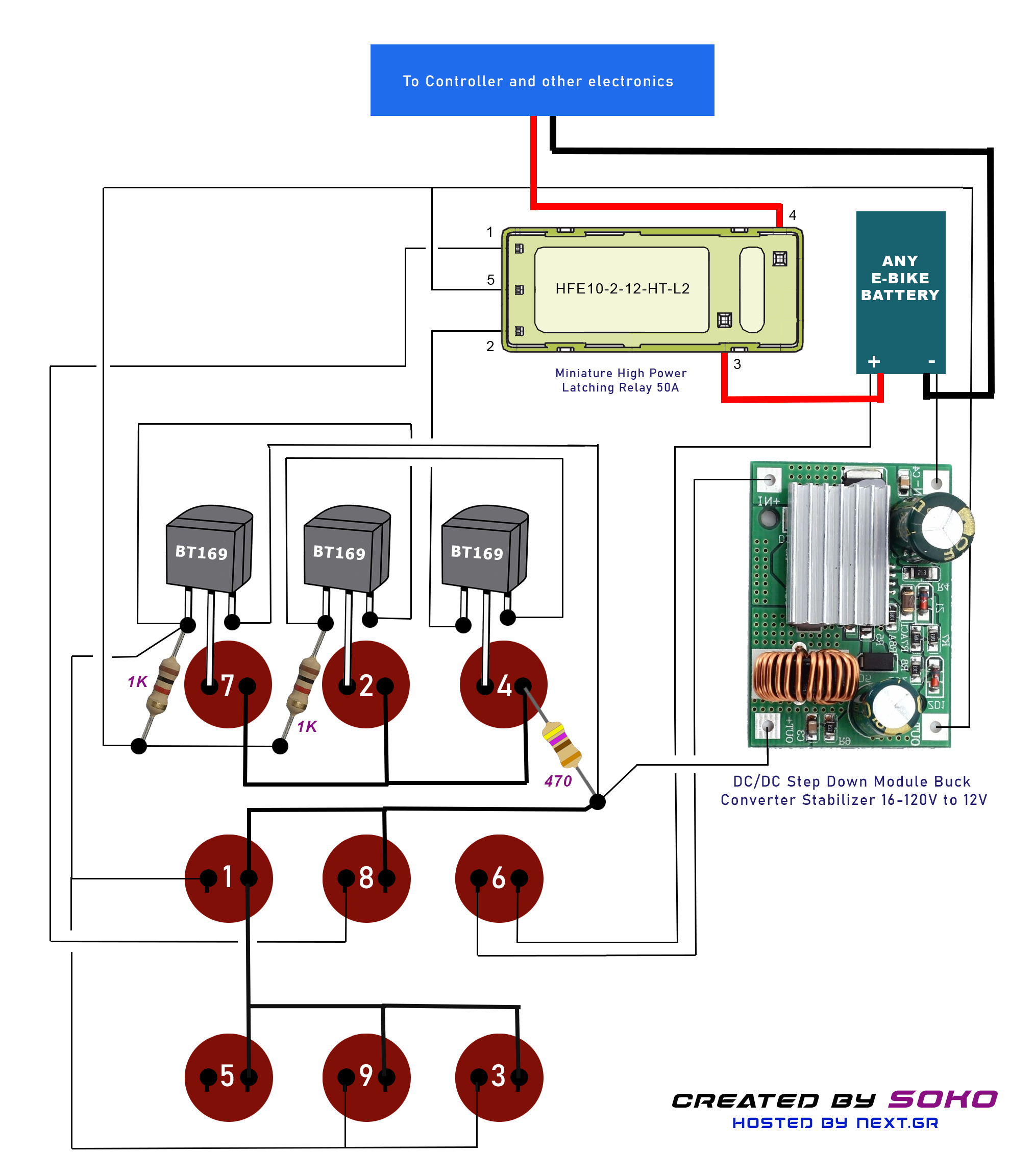
This project is designed for a custom-made battery casing that provides ample space for concealing components. The switch can be adapted for various projects but is specifically tailored to meet e-bike requirements. It utilizes a clever thyristor functionality to...
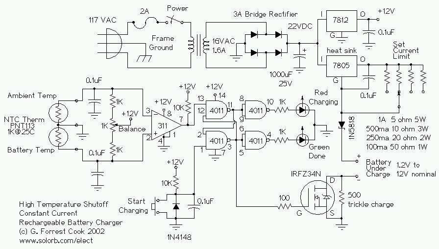
This circuit is designed for a temperature-controlled constant current battery charger, compatible with NiCd, NiMH, and other rechargeable cells. It operates on the principle that most rechargeable batteries exhibit an increase in temperature when they are fully charged. Overcharging...
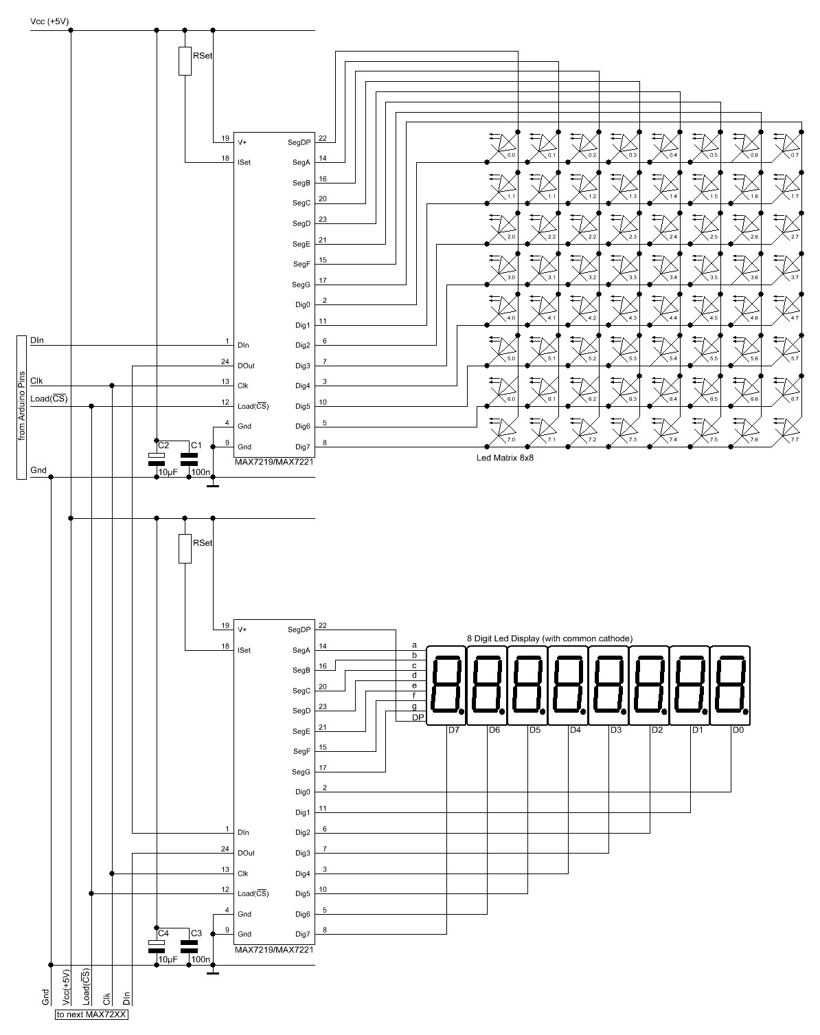
The Arduino website provides comprehensive documentation on connecting LEDs to the Arduino using the MAX7221. A specific set of components is required for this setup. The MAX7221 is a versatile LED driver that enables the control of multiple LEDs through...
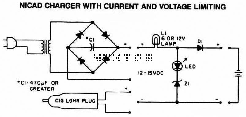
The following diagram is the schematic of a Ni-CAD battery charger circuit, which includes current and voltage limiting features to extend the battery's lifespan. The lamp L1 will illuminate brightly, and the LED will be off when the battery...
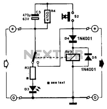
A charged capacitor C3 and a momentary pushbutton switch S2 are utilized to temporarily activate relay RE2. The battery being charged powers the relay to maintain its closed state. Additionally, S2 can energize the relay even if the battery...
Typically, a charged lead-acid battery and a power inverter are utilized to ensure a well-organized holiday where family members can enjoy their electric and electronic devices. With rechargeable lead-acid batteries, it is often beneficial, if not essential, to determine...