
battery charging indicator for

The circuit described utilizes a basic current detection mechanism to monitor the charging process of NiCd batteries. The adjustable mains adapter provides the required voltage, while the current indicator circuit ensures that the charging current can be monitored effectively. The LED indicator is an essential component, as it provides visual feedback regarding the charging status.
The circuit operates by employing a transistor (BU406) with its base connected to a resistor (R1) that is in series with the battery. When the current flowing through the resistor exceeds the threshold voltage of approximately 0.2 V, the transistor turns on, allowing current to flow through the LED, which subsequently illuminates. The choice of resistor value is crucial; a lower resistance value will result in a higher current threshold for the LED to light up, while a higher resistance will allow the LED to activate at a lower current, providing flexibility depending on the specific battery charging requirements.
The circuit is designed to maintain efficiency and safety. The transistor's ability to absorb excess current beyond the 0.7 V threshold ensures that it operates within safe limits, preventing damage to the circuit components. The TO-220 package of the BU406 transistor provides adequate heat dissipation capabilities, which is essential when handling higher currents.
Overall, this circuit serves as a practical solution for charging incompatible NiCd batteries, providing a simple yet effective method to monitor charging status while ensuring that the charging current remains within safe operational limits.Although you may well be the proud owner of the very latest NiCd battery charger, you may still come across the odd `incompatible` battery, for example, one having a rare voltage or requiring a much higher charging current than can be supplied by your off-the-shelf charger. In these cases, many of you will resort to an adjustable mains adaptor (sa y, a 500-mA type) because that is probably the cheapest way of providing the direct voltage required to charge the battery. Not fast and not very efficient, this `rustic` charging system works, although subject to the following restrictions: You should have some idea of the charging current.
In case you use an adaptor which is adjustable but of the unregulated, low output current type, you can adjust the current by adjusting the output voltage. You have to know if the current actually flows through the battery. A current-detecting indicator is therefore much to be preferred over a voltage indicator. To prevent you from forgetting all about the charging cycle, the indicator should be visible from wherever you pass by frequently.
Using the circuit shown here, the LED lights when the baseemitter potential of the transistor exceeds about 0. 2 V. Using a resistor of 1 as suggested this happens at a current of about 200 mA, or about 40 mA if R1 is changed to 4.
7. The voltage drop caused by this indicator can never exceed the base-emitter voltage (UBE) of the transistor, or about 0. 7V. Even if the current through R1 continues to increase beyond the level at which UBE = 0. 7 V, the base of the transistor will `absorb` the excess current. The TO-220 style BU406 transistor suggested here is capable of accepting base currents up to 4A. Using this charging indicator you have overcome the restrictions 2 and 3 mentioned above. 🔗 External reference
Related Circuits
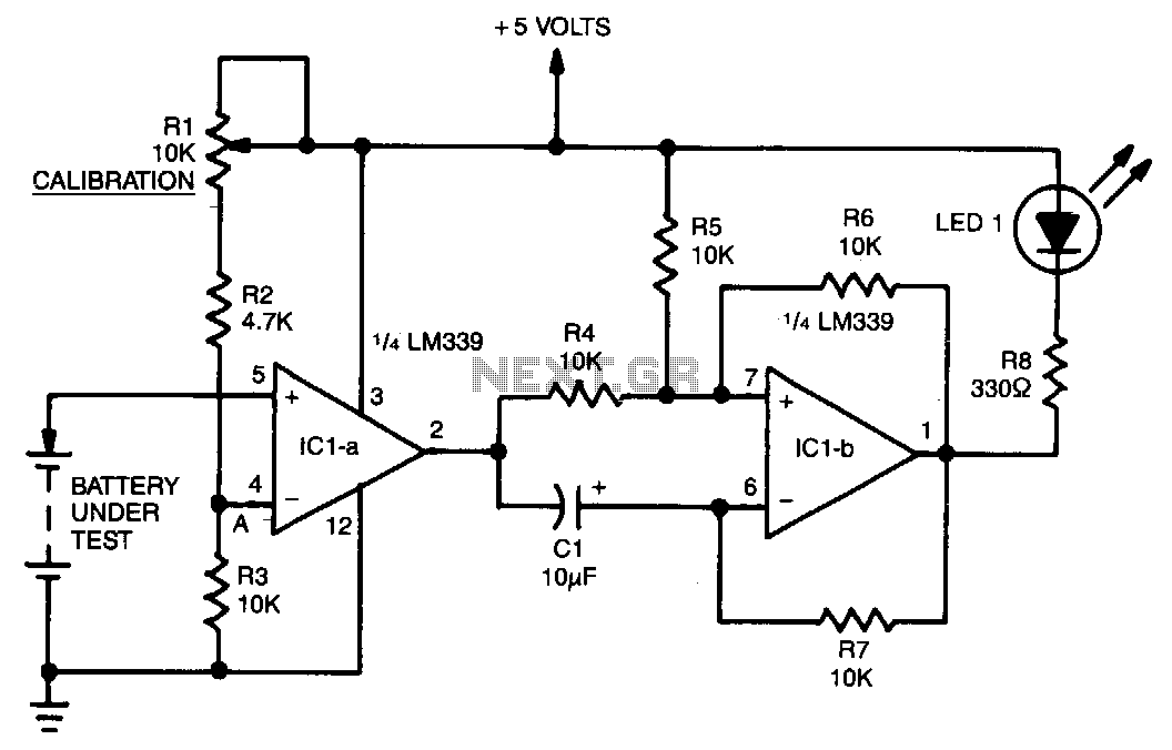
A voltage divider consisting of R1, R2, and R3 is utilized to establish the input reference voltage below which the batteries should be replaced. The reference voltage at point A is adjustable via R1. As illustrated in the diagram,...
The count switching circuit consists of an electronic switch and a pulse delay circuit for control. The count switching circuit is designed to manage the switching of signals in a controlled manner. The electronic switch serves as the primary component...

If the total circuit resistance can be significantly reduced to less than 0.1 Ohm and a load of 0.4 Ohm or less is connected, over 1 kilowatt of free electrical energy can be obtained. There are two discrete voltage...
This circuit can be utilized as a replacement for the single current-limiting resistor typically found in low-cost battery chargers. The alternative presented here is advantageous because it prevents the premature failure of nickel-cadmium (NiCd) batteries, which often occur after...
Have you ever been using the modem or fax and someone else picks up the phone, breaking the connection? Well, this simple circuit should put an end to that. It signals that the phone is in use by lighting...
Almost all 24V power systems in trucks, 4WDs, RVs, boats, etc., utilize two series-connected 12V lead-acid batteries. The charging system can only sustain the total voltage of the individual batteries. If one battery is failing, this circuit will illuminate...