
Battery Equality Monitor Circuit Schematic

The described circuit functions as a voltage monitoring system for dual 12V lead-acid batteries configured in series to create a 24V power supply. This configuration is prevalent in various applications, including trucks, 4WD vehicles, recreational vehicles (RVs), and marine vessels. The primary goal of the circuit is to provide early detection of battery health issues by monitoring the voltage levels of each battery.
The circuit utilizes a microcontroller or a simple comparator circuit to measure the voltage across each battery. By comparing the voltages, the circuit can determine if one of the batteries is underperforming or failing. When a significant voltage difference is detected, indicating that one battery is not holding its charge as well as the other, an LED indicator is activated. This visual alert serves as a warning to the user, allowing for timely intervention before complete battery failure occurs.
In terms of design, the circuit should include necessary components such as resistors to limit current to the LED, a voltage divider to scale down the battery voltages to a manageable level for the comparator or microcontroller, and possibly a relay if further actions are required, such as disconnecting the failing battery from the circuit. Additionally, the idle current consumption of the circuit must be minimized, allowing it to remain connected across the batteries without draining them excessively.
Overall, this monitoring circuit enhances the reliability of 24V systems by providing critical feedback on battery health, thereby prolonging the lifespan of the batteries and ensuring the uninterrupted operation of connected systems.Almost all 24V power systems in trucks, 4WDs, RVs, boats, etc, employ two series-connected 12V lead-acid batteries. The charging system can only maintain the sum of the individual battery voltages. If one battery is failing, this circuit will light a LED. Hence impending battery problems can be forecast. The circuit works by detecting a voltage difference between the two series connected 12V batteries. Idle current is low enough to allow the unit to be permanently left across the batteries 🔗 External reference
Related Circuits
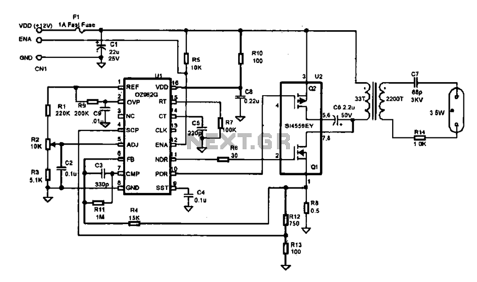
This document describes an efficient inverter control circuit designed for use as an LCD backlight power supply. The circuit is primarily managed by the chip UL (02962G), which interfaces with a driving field-effect transistor (U2), a voltage transformer, the...
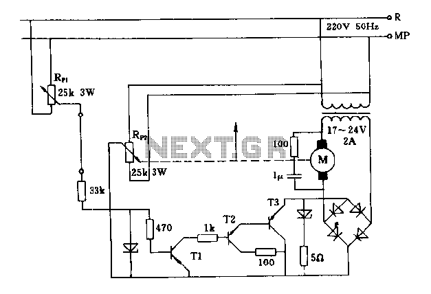
The FIG potentiometer RP2 has a sliding contact that is directly connected to the antenna. The system operates such that only when potentiometers RP1 and RP2 are positioned identically, do the non-conductive transistors and rectifier bridge remain off, resulting...
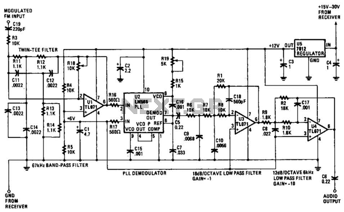
The operational amplifier (Op Amp) U1 and its associated components form a 67-kHz bandpass filter. A twin-T network, consisting of four 1100-ohm resistors and four 0.0022-microfarad capacitors, is integrated into the feedback loop of the op amp. This configuration...
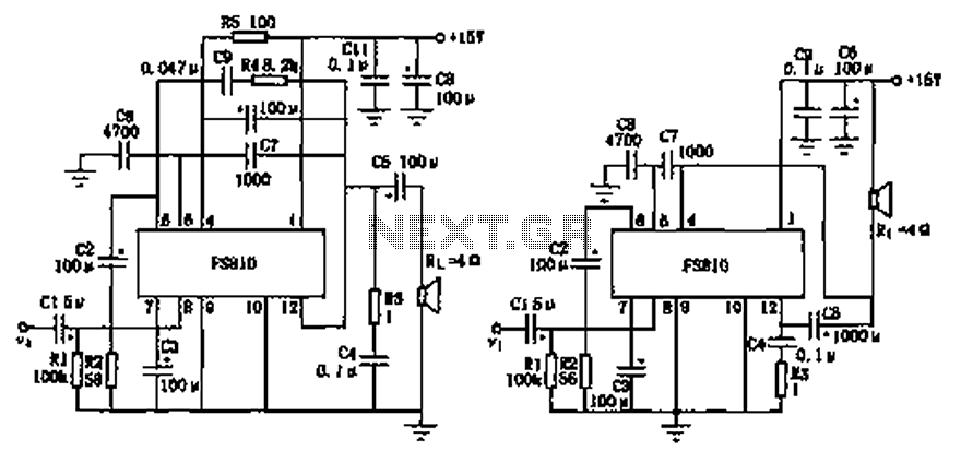
The FS810 circuit serves as a practical implementation of an integrated power amplifier. The FS810 is designed for high-performance use in high-end tape recorders and audio equipment. In the schematic, the speaker is connected to the output capacitor C5...
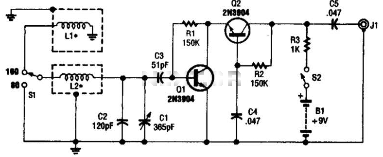
This antenna may assist in minimizing power-line noise. It consists of a plastic hula hoop or conduit with a diameter of 3 feet, which is covered with aluminum foil to serve as a shield for LI and L2. LI...
The LAN tester circuit can also test cables such as telephone, coaxial, LAN, and others. This circuit uses LEDs as the main indicator device. The LAN tester circuit is designed to verify the integrity and functionality of various types of...