
Cable LAN Tester Circuit

The LAN tester circuit is designed to verify the integrity and functionality of various types of cables, including telephone lines, coaxial cables, and LAN cables. The primary function of this circuit is to ensure that the connections are properly established and that there are no breaks or shorts in the wiring.
The circuit typically consists of a transmitter and a receiver module. The transmitter unit is connected to one end of the cable under test, while the receiver unit is connected to the other end. When the transmitter sends a signal through the cable, the receiver is able to detect this signal, indicating that the cable is functioning correctly.
LEDs are utilized as the main indicators in this circuit. These LEDs light up in response to the signals received, providing a visual confirmation of the cable's status. For example, a green LED may indicate a good connection, while a red LED could signify a fault or disconnection in the cable.
The circuit can be designed to accommodate multiple cable types by incorporating different testing modes. This may involve the use of switches or jumpers to select the appropriate testing configuration based on the type of cable being tested. Additionally, the circuit may feature a simple design that allows for easy assembly and troubleshooting, making it accessible for both professionals and hobbyists.
In summary, the LAN tester circuit is a versatile and essential tool for anyone involved in network installation and maintenance, ensuring that all types of cables are functioning properly and efficiently.cable LAN tester circuit can also to test cable on telephone, coaxial cable, Lan cable and other. this circuit using led for main indicator device 🔗 External reference
Related Circuits
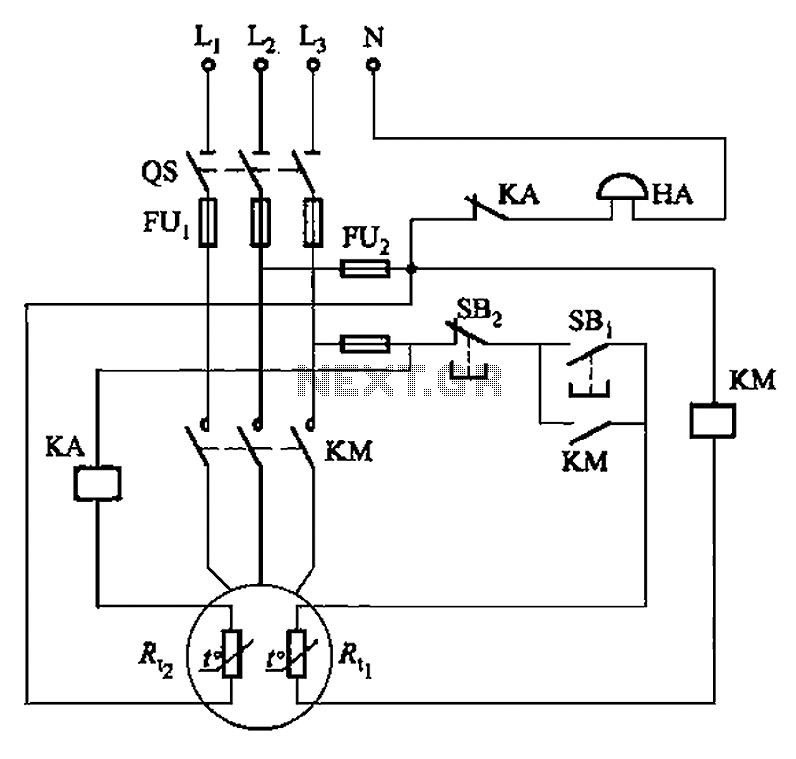
The circuit illustrated in Figure 4-2 employs two thermal resistors. One, designated as Rc, functions as overload protection, while the other, labeled Rt, serves as an alarm. The circuit in question integrates two thermal resistors to monitor temperature changes and...
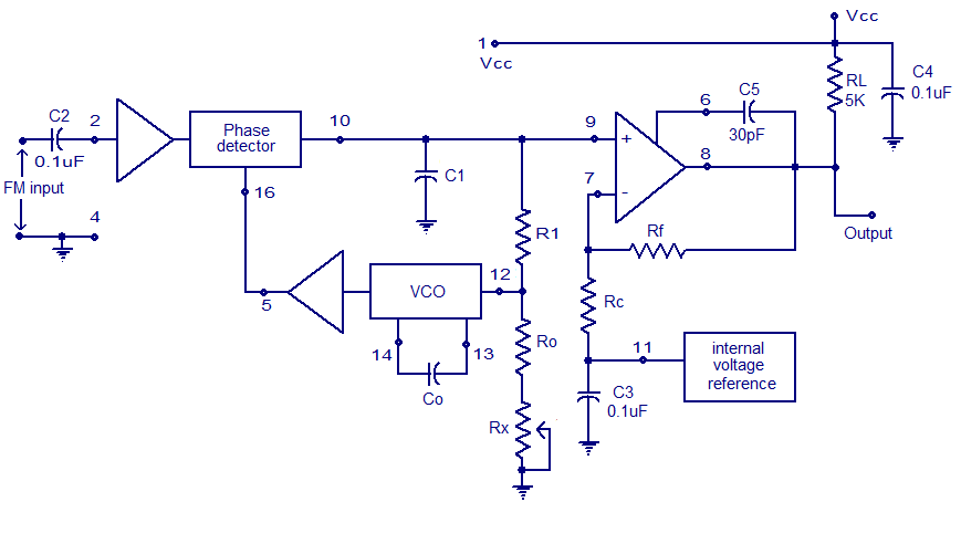
A simple PLL FM demodulator circuit using the IC XR2212 is presented. The XR2212 is a highly stable, monolithic PLL (phase-locked loop) IC specifically designed for communication and control system applications. It operates within a frequency range of 0.01...

This circuit provides protection for telephones, EPABX systems, telephone modems, and similar devices against lightning discharges and line voltage spikes. It incorporates a safety capacitor and gas discharge components. The circuit employs a safety capacitor to filter out high-frequency noise...
This LC meter circuit is capable of measuring inductors and capacitors. When either Lx or Cx is connected to the circuit, the oscillator frequency decreases, and this reduction is measured by a frequency-voltage converter constructed with transistors T3 and...
Figure 7-2 illustrates the FSK (Frequency Shift Keying) signal demodulation circuit, which is built using a digital phase-locked loop. This circuit features two oscillators operating at distinct frequencies: crystal oscillator X with a frequency of 983.04 kHz and crystal...
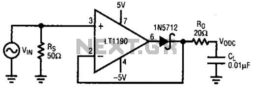
This closed-loop peak detector circuit utilizes a Schottky diode within the feedback loop to achieve high accuracy. The 20-ohm resistance RQ serves to isolate the 0.01-ohm load and prevent oscillations. The direct current (DC) value is measured using a...