
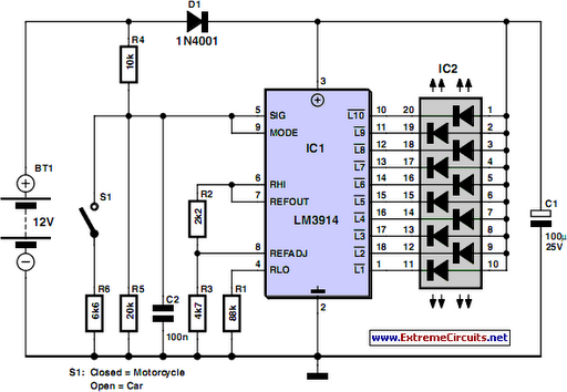
battery equality monitor circuit schematic

The described circuit serves a critical role in monitoring the health of a dual-battery system commonly found in various vehicles and marine applications. It is designed to provide a visual alert for battery failure, which is essential for preventing unexpected breakdowns or failures during operation.
The circuit consists of a voltage sensing mechanism that compares the voltage levels of the two batteries. Typically, this is achieved using a differential amplifier or a microcontroller with analog-to-digital conversion capabilities. The output from this sensing mechanism is fed into a comparator circuit that activates an LED when a significant voltage difference is detected, indicating that one of the batteries is underperforming or failing.
The low idle current characteristic of the circuit is crucial, as it allows for continuous monitoring without draining the batteries over time. This feature is particularly important in applications where the vehicle may not be used for extended periods, ensuring that the monitoring system does not contribute to the very problems it is designed to detect.
In practical implementation, the circuit can be housed in a weather-resistant enclosure to protect it from environmental factors, especially in marine or off-road applications. Additionally, the choice of components should consider the operating temperature range and vibration resistance, as these factors can affect the reliability of the circuit in harsh conditions.
Overall, this battery monitoring circuit is an invaluable tool for maintaining the integrity and performance of 24V power systems, ensuring that potential issues are identified and addressed before they lead to more serious failures.Almost all 24V power systems in trucks, 4WDs, RVs, boats, etc, employ two series-connected 12V lead-acid batteries. The charging system can only maintain the sum of the individual battery voltages. If one battery is failing, this circuit will light a LED. Hence impending battery problems can be forecast. The circuit works by detecting a voltage difference between the two series connected 12V batteries. Idle current is low enough to allow the unit to be permanently left across the batteries.. 🔗 External reference
Related Circuits
Camping today often requires various electronic devices for daily activities and entertainment. Typically, a charged lead-acid battery and a power inverter are utilized to ensure a well-organized trip, allowing family members to enjoy their electronic equipment. It is essential...
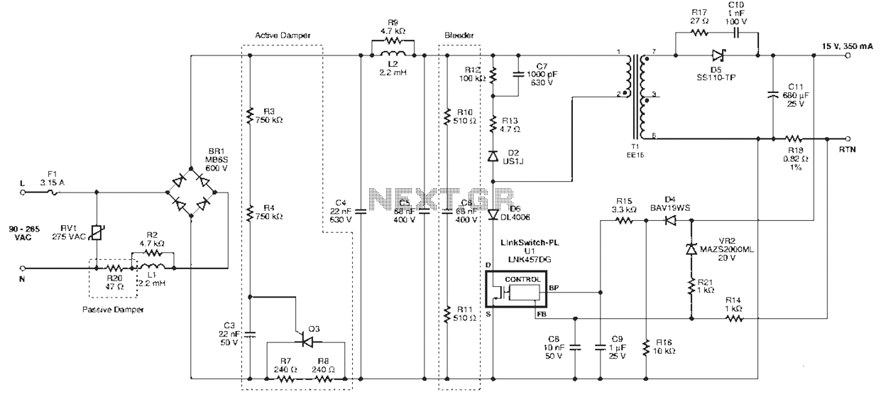
Power Integrations' DER322 reference design employs the LinkSwitch-PL family of LNK460VG devices. This design represents the industry's first alternative 100W A19 incandescent LED driver utilizing a single-layer PCB. It is characterized by low cost, minimal component count, and compact...
This circuit below shows a teleremote circuit that enables the switching on and off of appliances through telephone lines. The teleremote circuit utilizes a telephone line as a medium for controlling electrical appliances from a distance. The primary components...
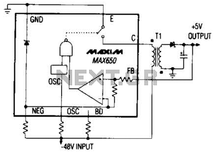
The Max650 switching regulator generates a regulated 5 V output from large negative voltages, such as the -48 V commonly found on telephone lines. This power supply requires several external components, including a transformer, and is capable of delivering...
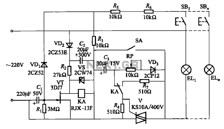
The circuit illustrated in Figure 2-50 utilizes a field effect tube and a combination of electronic components to create a unique self-lighting controller. The working lamp remains illuminated at a reduced brightness rather than being completely turned off, which...
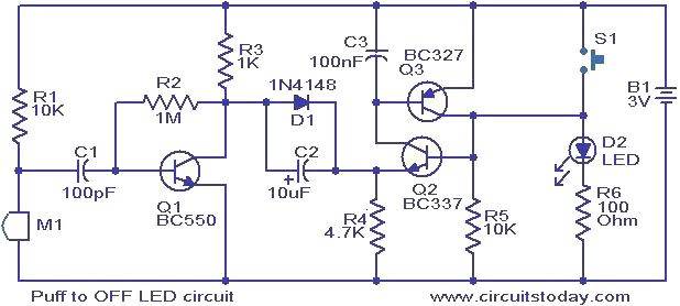
This circuit features an LED that can be turned off with a puff of air. A condenser microphone (M1) detects the puff. When the push button switch S1 is activated, transistors Q2 and Q3, configured as a latching pair,...