
Battery indicator

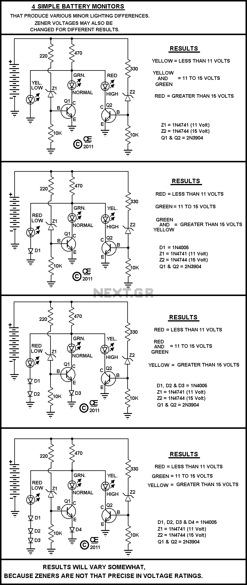
This circuit is designed to monitor battery voltage levels while ensuring minimal power consumption. The primary component, Tr1, is a transistor that operates in a low-power state, drawing approximately 250 microamperes. This low consumption is crucial for applications where battery life is a priority.
As the battery voltage approaches a predefined threshold, Tr1 ceases operation, which triggers Tr2 to activate. Tr2 is responsible for driving a low current LED diode. The LED serves not only as an indicator of the circuit's status but also increases the current draw from the battery. This additional load assists in reaching a clear and distinct turn-off point for the circuit, ensuring that the battery is not over-discharged, which could lead to damage.
The use of a low current LED diode is essential in this design, as it allows for visual feedback without significantly impacting the overall power consumption. The circuit can be applied in various battery-operated devices where monitoring battery status is critical, such as portable electronics or remote sensors.
In summary, this battery monitoring circuit effectively balances low power consumption with functionality, leveraging transistors for control and an LED for user indication, thereby enhancing the reliability and longevity of battery-powered applications.Continually monitors battery voltage during use and consumes only about 250 ? A (until the end point is reached). Near the end point Trl turns off, allowing Tr2 to illuminate the LED to increase current drain further leading to a distinct turn off point. Use a low current LED diode.
Related Circuits
A novel supply voltage monitor which uses a LED to show the status of a power supply. This simple and slightly odd circuit can clearly show the level of the supply voltage (in a larger device): as long as...
A Very Simple circuit and some Variations. Play with it. All parts are cheap and should be easily obtained. None are very critical. The circuit in question is a basic electronic assembly designed for educational purposes and experimentation. It typically consists...

This circuit delivers an initial voltage of 2.5V per cell to rapidly charge a car battery. The charging current decreases as the battery charges. This circuit is designed to provide an efficient charging solution for car batteries by applying an...
The Over-the-Top type of operational amplifier is ideal for use as a current sense for battery charger applications. The design described here can be used. The Over-the-Top operational amplifier (op-amp) is specifically designed for applications requiring precise current sensing, particularly...
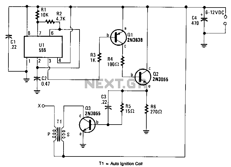
An output voltage sufficient to bridge a one-inch gap can be generated from a 12-V power source. A 555 timer integrated circuit (IC) is configured as an astable multivibrator, producing a narrow negative pulse at pin 3. This pulse...
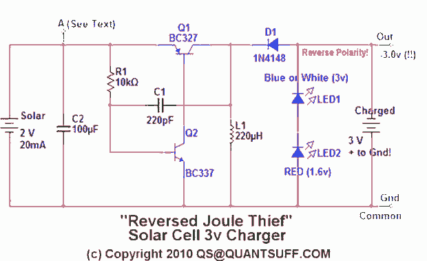
This design presents an innovative approach to the Joule Thief (JT) circuit typically utilized in garden lights. Instead of directly charging a 1.2V battery from the solar cell and converting the power to operate a 3-volt LED, this circuit...