
Supply Voltage Indicator

The described voltage monitor circuit is designed to provide visual feedback on the status of a power supply through the use of two LEDs, LED1 and LED2, each indicating different voltage thresholds. The circuit operates within a specified voltage range, monitoring input voltages from approximately 9 V to 14 V.
When the input voltage is at or above 12 V, LED1 emits a steady yellow light, indicating that the power supply is functioning within an acceptable range. As the voltage decreases below 11 V, LED1 begins to blink. The frequency of the blinking decreases progressively with further drops in voltage, providing an intuitive representation of the power supply's condition. This feature allows users to quickly assess the health of the power supply at a glance. Once the voltage drops below 9 V, LED1 extinguishes, signaling that the power supply is no longer operating within safe limits.
Conversely, when the input voltage exceeds 13 V, LED2 activates, emitting light that increases in intensity as the voltage approaches 14 V. This serves as an alert for over-voltage conditions. The design allows for user adjustments of the voltage thresholds, enabling customization based on specific application requirements.
The circuit likely employs voltage divider networks and comparator circuits to detect the voltage levels and control the LEDs accordingly. A microcontroller or an operational amplifier may be utilized to manage the blinking behavior of LED1, ensuring precise control over the frequency of the blinking as the voltage decreases.
In summary, this voltage monitor circuit is an effective tool for visually indicating both under-voltage and over-voltage conditions, enhancing the reliability and safety of electronic devices by providing clear and immediate feedback on the power supply status.A novel supply voltage monitor which uses a LED to show the status of a power supply. This simple and slightly odd circuit can clearly show the level of the supply voltage (in a larger device): as long as the indicator has good 12 volts at its input, LED1 gives steady, uninterrupted (for the naked eye) yellow light. If the input voltage falls below 11 V, LED1 will start to blink and the blinking will just get slower and slower if the voltage drops further - giving very clear and intuitive representation of the supply`s status.
The blinking will stop and LED1 will finally go out at a little below 9 volts. On the other hand, if the input voltage rises to 13 V, LED2 will start to glow, getting at almost full power at 14 V. The characteristic voltages can be adjusted primaril 🔗 External reference
Related Circuits
A keyed power input connector, series rectifier and a shunt rectifier, both 1N4007, prevent reverse voltage from being applied to the power input. A 27 volt metal oxide varistor clamps the voltage to the 78L05 that follow it, to...
A power transistor with a voltage drop of 4 volts and a current of 3 amps may dissipate approximately 12 watts of heat, presenting a challenge in series regulators. In contrast, a saturated transistor or MOSFET with a voltage...
The 7915 (at least the "made in Morocco" I used) needs a small load (some mA) to work correctly. If you get funny voltages (-18.4V or so), put a resistor from the 7915 output to ground (2k2 works good)....
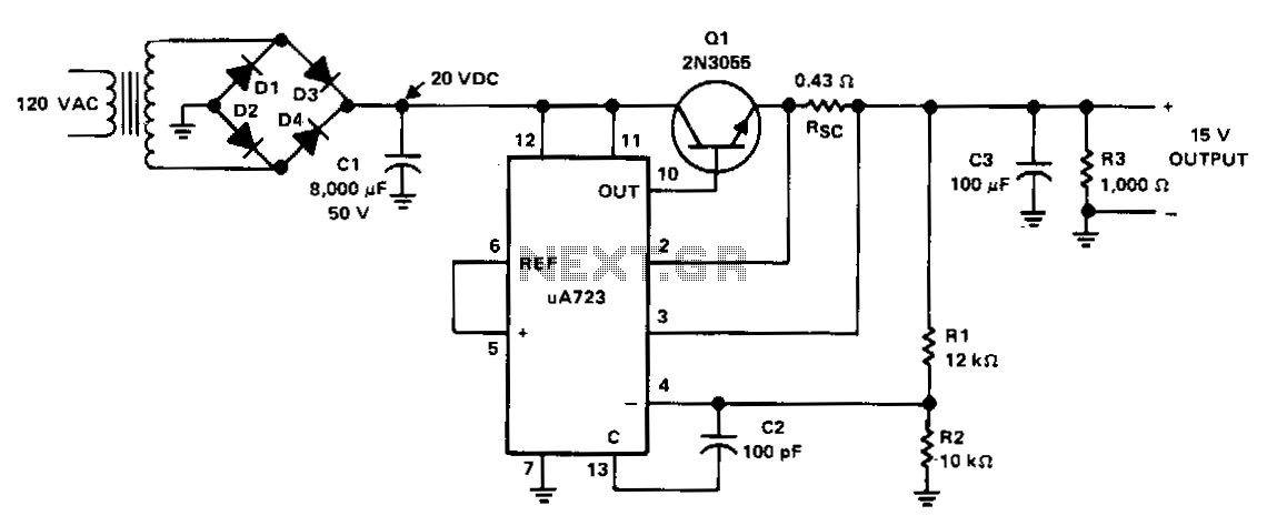
The power supply receives +20 VDC from the rectifier/filter section. This voltage is applied to pins 11 and 12 of the uA723 voltage regulator, as well as to the collector of the 2N3055 series-pass transistor. The output voltage is...
Most ohmmeters of the design shown in the previous section utilize a battery of relatively low voltage, usually nine volts or less. This is adequate for measuring resistances under several mega-ohms (MΩ), but when extremely high resistances need to...

This circuit is designed for higher input or output voltages in an L200 voltage regulator. It addresses issues that arise when input or output voltages exceed the regulator's specifications. The circuit incorporates external components, including a transistor that absorbs...