
battery isolator

The circuit design employs a 6V automotive relay (RLY1) that acts as a switch to control the operation of a Continuous Duty Solenoid (RLY2). The solenoid is crucial for managing the connection between the primary battery and the auxiliary battery, ensuring that both batteries can be charged while the engine is running. The relay is activated by the voltage generated from the vehicle's alternator stator, which typically provides a consistent voltage output when the engine is operational.
The Continuous Duty Solenoid is rated for continuous operation, allowing it to handle the load necessary for maintaining the parallel connection of the batteries without overheating or failing. This design is particularly beneficial for applications where auxiliary power is required, such as powering camping accessories or other electrical devices without draining the primary battery.
The automatic operation of the system is a significant advantage, as it eliminates the risk of forgetting to engage or disengage the battery connection. When the engine is turned off, the drop in voltage from the alternator stator results in the relay deactivating, which in turn cuts off the power to the solenoid. This ensures that the secondary battery is isolated, preserving its charge for future use.
Overall, this circuit provides a reliable and efficient solution for managing battery connections in vehicles, particularly for those used in recreational applications where auxiliary power is essential. The integration of the relay and solenoid into the system simplifies the operation and enhances the reliability of the vehicle's electrical management.This circuit is even simpler and employs a 6V feed from one of the stator connections on the vehicle`s alternator. This is connected to a 6V automotive relay (RLY1) which controls a Continuous Duty Solenoid (RLY2). This solenoid electrically connects or isolates the batteries. When the engine is started and the alternator stator voltage rises, the 6V relay turns on. This turns on the Continuous Duty Solenoid to connect the two batteries in parallel. As long as the engine is running, the vehicle`s alternator will maintain charge in both batteries. When the engine is shut down, the alternator stator voltage drops and the Continuous Duty Solenoid switches off, thus isolating the second battery from the vehicle`s electrical system. Provided that camping accessories are only connected to the second battery, the main battery should never discharge.
Because the concept is entirely dependent upon the alternator`s stator output voltage, you cannot forget to turn the system on or off as it happens automatically. 🔗 External reference
Related Circuits
Widely available AA NiMH battery chargers are on the market, including those packaged to charge various battery types such as NiCd and NiCad. This project features a battery charger designed for two AA NiMH or NiCd cells of any...
A car battery deteriorates with use, typically lasting no more than four years. Initially, its voltage may drop to just 2V when cranking the engine. As the battery ages, its internal impedance increases, leading to a higher voltage drop...

This circuit delivers an initial voltage of 2.5V per cell to rapidly charge a car battery. The charging current decreases as the battery charges. This circuit is designed to provide an efficient charging solution for car batteries by applying an...
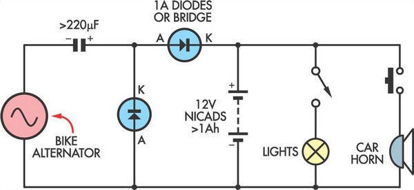
This simple circuit enables a 12V battery pack to be charged using a bike generator. The generator is rated at 3W and, with the inclusion of a voltage multiplier circuit, delivers approximately 200mA at a speed of around 15...
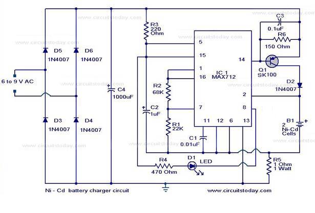
The following circuit illustrates a super fast Ni-Cd battery charger. It is based on the IC MAX 712 and is designed to charge a Ni-Cd battery at a rate of 300 mA. The circuit utilizes the MAX 712 integrated circuit,...
The Over-the-Top type of operational amplifier is ideal for use as a current sense for battery charger applications. The design described here can be used. The Over-the-Top operational amplifier (op-amp) is specifically designed for applications requiring precise current sensing, particularly...