
Battery Meter for Pinball Machines

The circuit is designed for 4. 5 volt battery packs (3 cell x 1. 5 volts). T he circuit gives level indication using 3 LED`s - one green (good), one amber/yellow (mid) and one flashing red LED indicating low battery power - 3. 2v or less approx. I think a 1. 3-1. 5 volt drop should be enough warning - I can`t guage the drop-out voltage for CMOS memory standby in WPC games because of the ASIC, so, I`ve gone for what you see here.
3 comparators compare the incomming battery voltage against 3 reference voltages provided by 3 potential dividers (see schematic), the 3 comparators directly drive the LED`s by sinking current to ground (internal). On power-up, the Green LED will always be on indicating good battery power. As the battery voltage drops, the amber LED will light, followed by the red flashing LED, the previous LED`s remain on until all the LED`s are lit.
I designed the circuit in this manner to cut down the component count and make the building easier. If you wish to modify the circuit so that LED`s will extinguish one after the other - I suggest you use a 74HC03 quad NAND gate with open-drain outputs to sink the LED current, and, who`s input`s is switched by next comparator in sequence thereby turning the previous gate off (I would have given the schematic details here but I don`t have the IC handy to incorporate into the design at the time). IMPORTANT NOTE: If your battery pack provides 4. 21 volts or greater when new then all the leds will remain off. In most cases, new batteries do not always put out their specified voltage - a small voltage drop is usual.
The potential divers - R1+R2, R3+R4 and R5+R6 provide the reference voltages. If you wish to modify the circuit to output different references, then the potential divider voltage can be given by the formula: The circuit should fit on a board 2"x 2". Build the potential divders/voltage references first, supply them with +5 volts and ground (don`t forget capacitors C1/2) and measure the output - they should be approx the figures given.
Next:- add a 14 pin socket (absolutely vital) to the board and run the reference voltages to the correct pins according to the schematic, then +5 volts and ground - now measure the voltages at the socket to ensure they`re present. Next:- add the 330 ohm LED current limiting resistors R10-R12 followed by the LED`s to the board (or mount them on small flyleads for fitting to the box cover).
Last but not least - add the LM or CA339 quad comparator and power up. You should have the green LED on (exception, battery >4. 21v) - now rotate the 10k pot and the LED`s should light in sequence - green, amber then flashing red. If they do not then power down and CHECK YOUR CONNECTIONS. If the circuit works correctly then removed the Vbat sim. and add the 3 flyleads to allow connection to the MPU board of your game. I suggest you use a red wire for +5 volts, a black wire for ground and another wire of you choice for the Vbat line.
Add all the bits into a little box and mount the box onto the backbox wall. I suggest that you actually drill holes in the cover for the LED`s to protrude through, or, connect them to the board with small flyleads and glue them into the box cover. Solder the flyleads to the MPU board with the POWER OFF. Allow the board 2 minutes before soldering in the leads as the onboard capacitors may still hold a charge.
USE COMMON SENSE! - don`t tap the +5 volts for the circuit from a chip leg - find a free pad on the board that you can tap from. Wire the battery power from the pack were it enters the board and return to a suitable earth point. KEEP IT NEAT! - Take pride in you work - make the flyleads t 🔗 External reference
Related Circuits
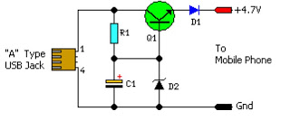
This simple circuit provides a regulated output of 4.7 volts for charging mobile phones. A USB outlet delivers 5 volts DC at a current of 100 mA, which is adequate for slow charging of mobile devices. Most mobile phone...
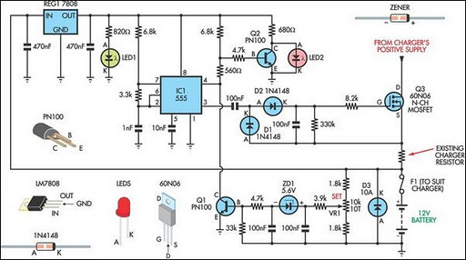
Most commercial car battery chargers cannot be left connected to the battery for extended periods, as this can lead to overcharging and subsequent battery damage. This add-on circuit is connected in series with the battery being charged and is...
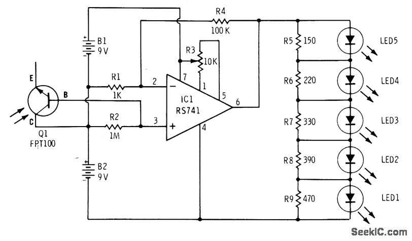
The phototransistor Q1 (Radio Shack 276-130) activates a voltage change across resistor R2, which is then amplified by an operational amplifier (op-amp). The output from the op-amp drives an array of five LEDs, creating a bar graph voltage indicator....

RF based Automatic meter reading, or AMR, is the technology of automatically collecting data from energy meter and transferring that data to a central database for billing and/or analyzing. This means that billing can be based on actual consumption...

This is a circuit using the LM3914 LED VU meter. It utilizes the LM3914 integrated circuit (IC1) along with a BC109C transistor. The circuit displays the level of audio signals (power music) in decibels (dB) across six levels using...
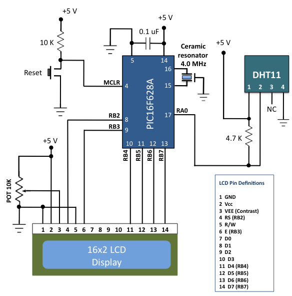
The DHT11 is the most affordable sensor currently available in the market that provides calibrated digital outputs for temperature and relative humidity. The DHT11 sensor is a low-cost digital sensor that measures both temperature and relative humidity. It operates...