
Battery Charger Regulator

This circuit design addresses the common issue of overcharging in traditional car battery chargers by incorporating a smart control mechanism. The high-current MOSFET serves as the primary switching device, efficiently managing the flow of current to the battery. The use of a 555 timer configured as an astable oscillator allows for precise timing control, ensuring that the MOSFET operates at the optimal frequency for gate voltage generation. The diode pump configuration (D1 and D2) is essential for boosting the gate voltage of the MOSFET, which is crucial for achieving low on-resistance and thereby minimizing power loss during operation.
The three-terminal regulator (REG1) plays a vital role in providing a stable voltage supply for the circuit's operation, ensuring that the components function reliably regardless of variations in the battery voltage. The inclusion of LED1 serves a dual purpose: it provides a visual indication of the charger’s operational status and confirms that the battery connection is secure.
The monitoring of the battery voltage through the 10 kΩ potentiometer (VR1) allows for user adjustments and fine-tuning of the voltage threshold at which the charging process will cease. This feature enhances the circuit's adaptability to different battery types and conditions, making it suitable for a variety of applications.
Overall, this add-on circuit effectively mitigates the risks associated with prolonged charging, ensuring that the battery is charged safely and efficiently, thereby prolonging its lifespan and enhancing performance.Most off-the-shelf car battery chargers cannot not be left connected to the battery for long periods of time as over-charging and consequent battery damage will occur. This add-on circuit is placed in series with the battery being charged and is powered by the battery itself.
In effect, the circuit uses a high-current Mosfet to control the chargin g current and it turns off when the battery voltage reaches a preset threshold. Power for the circuit is fed from the battery to 3-terminal regulator REG1 which provides 8V. LED1 indicates that the battery is connected and that power is available. The 555 timer IC is configured as an astable oscillator running at approximately 100kHz. It feeds a diode pump (D1 & D2) to generate adequate gate voltage for Mosfet Q3, enabling it to turn on with very little on resistance (typically 14 milliohms). With the Mosfet turned on, current flows from the charger`s positive terminal so that charging can proceed.
The battery voltage is monitored by 10kO pot VR1. 🔗 External reference
Related Circuits
An easy automatic battery charging circuit is presented, which can automatically power off when the battery is fully charged. This design prevents overcharging. The automatic battery charging circuit operates by utilizing a voltage sensing mechanism to monitor the battery's charge...
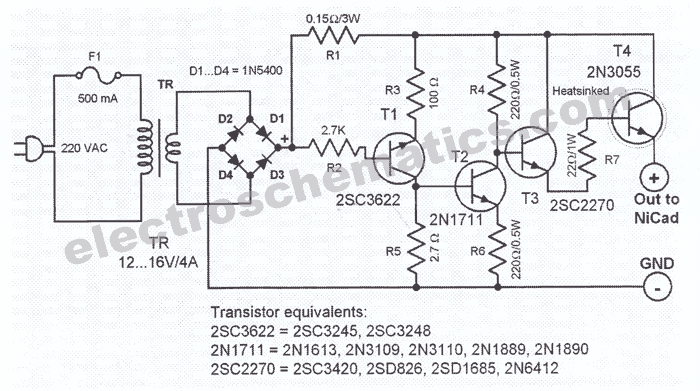
This NiCd battery charger circuit schematic can charge 6 volts as well as 12 volts NiCad batteries. It uses a transformer that can deliver 4 to 5 A current. The NiCd battery charger circuit is designed to accommodate both 6V...
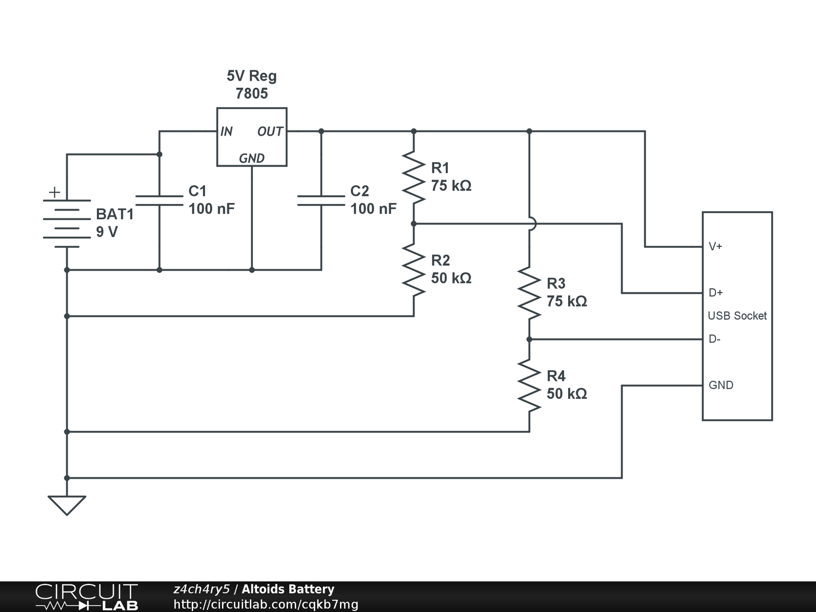
Instructions for creating a battery pack for Apple devices powered by standard alkaline batteries are provided. This overview outlines the circuit design for the battery pack, with detailed casing instructions to follow in a subsequent section. Note: When soldering...
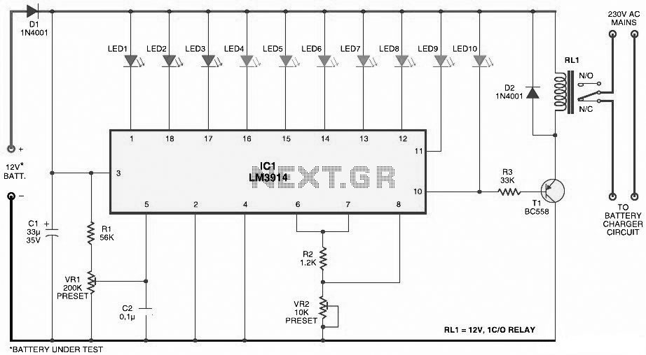
This document presents a circuit diagram for a simple and easy-to-construct battery level indicator. Typically, in mobile phones, battery levels are shown in either dot or bar format, allowing users to easily recognize the battery status. The battery level indicator...
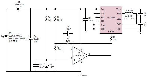
A simple supercapacitor charger electronic project can be designed using the LTC3625 integrated circuit (IC) from Linear Technology. This circuit is capable of charging two supercapacitors in series to a fixed output voltage of either 4.8V/5.3V or 4V/4.5V, which...
This circuit functions as a night lamp when a wall mains socket is unavailable for plugging in a continuously operating small neon lamp device. To minimize battery consumption, it utilizes a single 1.5V cell, and a simple voltage doubler...