
usb powered mobile phone battery

The circuit operates by utilizing a voltage regulation technique to ensure that the output remains stable at 4.7 volts, which is critical for the safe charging of mobile phone batteries. The choice of the NPN transistor Q1 is significant, as it must be capable of handling the required current without overheating. The Zener diode D2 serves as a voltage reference, ensuring that fluctuations in the input voltage do not affect the output voltage. The use of diode D1 is essential for protecting the circuit from potential damage caused by incorrect connections, particularly in situations where the USB plug may be inserted with reversed polarity.
The USB interface is designed to be user-friendly, with clear color coding for the connections. The red wire, typically associated with positive voltage, is connected to pin 1 of the USB plug, while the black wire, indicating ground, is connected to pin 4. This arrangement facilitates easy identification and connection, reducing the risk of incorrect wiring during assembly.
In practical applications, the circuit can be enclosed in a suitable housing to prevent damage and ensure user safety. It is advisable to include a fuse in the circuit for additional protection against overcurrent conditions. Furthermore, incorporating a small LED indicator could provide visual feedback on the charging status, enhancing user experience.
Overall, this circuit design offers a reliable and efficient solution for charging mobile phone batteries while prioritizing battery health through slow charging techniques.This simple circuit can give regulated 4. 7 volts for charging a mobile phone. USB outlet can give 5 volts DC at 100mA current which is sufficient for the slow charging of mobile phones. Most of the Mobile Phone batteries are rated 3. 6 volts at 1000 to 1300 mAh. These battery packs have 3 NiMh or Lithium cells having 1. 2 volt rating. Usually the ba ttery pack requires 4. 5 volts at 300-500 mA current for fast charging. But low current charging is better to increase the efficiency of the battery. The circuit described here provides 4. 7 regulated voltage and sufficient current for the slow charging of the mobile phone. Transistor Q1 is used to give the regulated output. Any medium power NPN transistor like CL100, BD139, TIP122 can be used. Zener diode D2 controls the output voltage and D1 protects the polarity of the output supply. Front end of the circuit should be connected to a A type USB plug. Connect a red wire to pin1 and black wire to pin 4 of the plug for easy polarity identification. Connect the output to a suitable charger pin to connect it with the mobile phone. After assembling the circuit, insert the USB plug into the socket and measure the output from the circuit. If the output is OK and polarity is correct, connect it with the mobile phone. 🔗 External reference
Related Circuits
The project involves using a Nokia 2300 mobile phone and its original earphones. The earphones function correctly for radio listening and phone conversations. However, the MT8870 integrated circuit does not provide output when connected to the AT89S52 microcontroller. A...

The circuit is designed to charge 2.4V, 4.8V, and 9.6V NiCd batteries. The LM317T integrated circuit (IC) shown in this NiCd battery charger schematic is utilized to regulate the voltage for charging the NiCd batteries. The LM317T IC has...
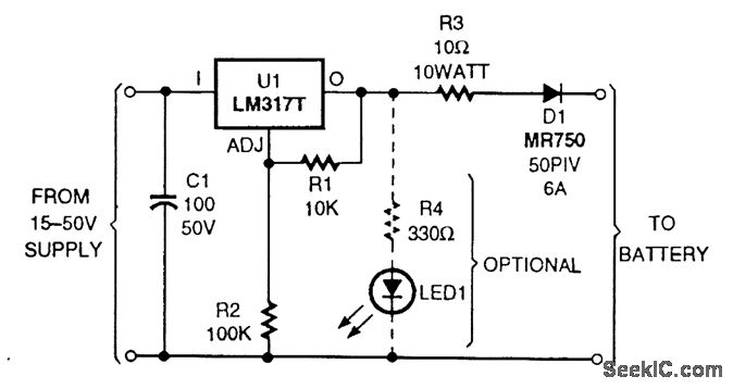
The circuit is based on an LM317T adjustable voltage regulator. The output voltage (VOUT) is defined by the formula VOUT = 1.25 (1 + R2/R1). A 10-kΩ resistor is selected for R1 and a 100-kΩ resistor for R2, allowing...
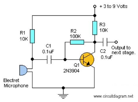
This project requires expensive hardware, including a microphone and amplifier, along with sophisticated audio analysis on the microcontroller. Even a complete microphone with an amplifier circuit does not yield the desired results, as noted in the product comments. The...
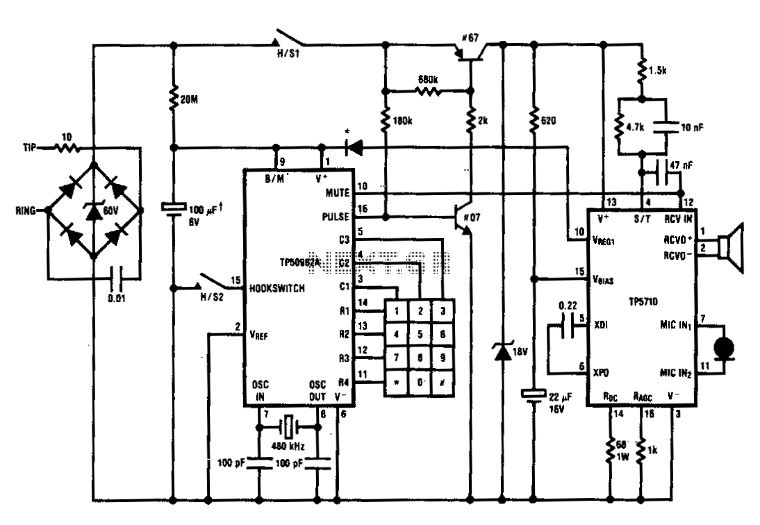
The TP5700 or TP5710 can reduce the number of components required to build a pulse-dialing telephone. The typical current source can be eliminated by utilizing the VREG1 output to power a TP50982A low-voltage (1.7 V) pulse dialer through a...
This circuit provides a regulated output voltage ranging from 5 V to 15 V DC, which can be adjusted using a preset resistor. The current output can reach up to approximately 350 mA. An integrated circuit is utilized to...