
Battery Operated LED Lantern

The described test circuit functions as a basic LED driver utilizing two transistors to control the current flow to the LED. The primary components include two NPN transistors, which are configured in a common emitter arrangement to amplify the input signal. The transistors are connected to a pair of resistors that set the biasing conditions and limit the base current to prevent damage to the transistors.
In this circuit, the white LED was initially used for evaluation purposes, providing a high brightness output suitable for flashlight applications. However, for practical implementation, a lower-cost green LED was substituted. The green LED operates at a different forward voltage, which may require adjustments to the resistor values to ensure optimal performance without exceeding the LED's current rating.
An additional consideration in the design is the incorporation of a voltage converter, which allows for the use of a single cell in a two-cell flashlight configuration. This converter steps up the voltage to the necessary level for the LED, enhancing efficiency and extending battery life. The LED assembly replaces traditional incandescent bulbs, offering advantages such as lower power consumption, longer lifespan, and improved durability.
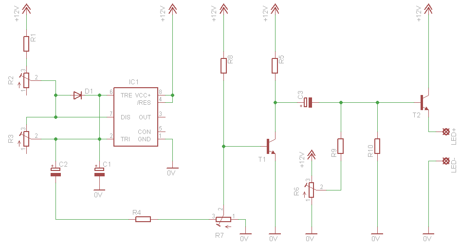
The circuit layout should be carefully designed to minimize parasitic capacitance and inductance, ensuring stable operation. Proper heat dissipation measures must also be considered, especially if the circuit is to be used in high-power applications. Overall, this basic driver circuit is a practical solution for LED-based lighting applications, demonstrating the versatility and efficiency of modern electronic components.Photo. This is the test circuit -the basic driver is only two transistors, two resistors, the circuit was evaluated using a white LED, but when it was time to button it up and archive it, I replaced the expensive white LED with a cheap green one. When Dave and I were kicking around ideas for the best arrangement of components for white led flashlight, Dave suggested putting the voltage converter in place of the second cell in a two cell flashlight, and substitute an LED assembly for the incandesce 🔗 External reference
Related Circuits
This is a simple 12V car battery charger circuit designed to address common issues found in most car battery chargers. One major problem is that if the charger remains on, the battery can overcharge, potentially damaging the charger plates...
This circuit will flash a bright red LED (5000 mcd) as an attention-getting device or fake car alarm. Component values are not critical, and other transistors may be used. The flash duration is determined by R2 and C1 and...
This circuit simulates a breathing or pulsing LED using a 555 timer chip. It has gained popularity, receiving numerous comments and emails from users who successfully built the circuit, as well as feedback from those who encountered difficulties when...

Transmitter RF Output LED Indicator Circuit Diagram. This RF output detector circuit, which includes a visual indicator, can be useful for an RF application. The transmitter RF output LED indicator circuit is designed to provide a visual representation of the...
The battery voltage is 1V for a low-frequency amplifying circuit, which can operate with a power supply voltage ranging from 1V to 1.7V, making it suitable for use with small batteries. The circuit provides an output power of 80mW...
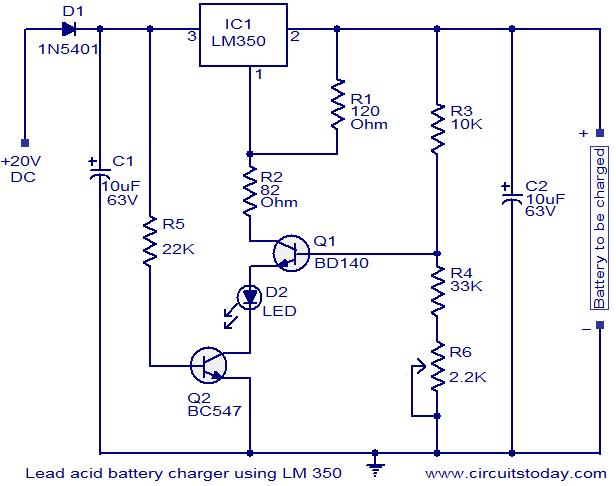
This circuit utilizes the IC LM350 for charging 12V lead-acid batteries, providing a constant voltage source with a negative temperature coefficient. The transistor Q1 (BD140) functions as a temperature sensor, while transistor Q2 prevents the battery from discharging through...