
Transmitter RF Output LED Indicator

The transmitter RF output LED indicator circuit is designed to provide a visual representation of the RF signal's presence and strength. This circuit typically consists of a few key components: a radio frequency (RF) detector, an LED indicator, and supporting passive components such as resistors and capacitors.
The RF detector is the core component, responsible for sensing the RF signal. It can be implemented using a diode or a specialized RF detection IC that converts the RF signal into a lower voltage DC signal. This conversion is essential for driving the LED indicator. The output of the RF detector is directly proportional to the strength of the incoming RF signal, allowing the circuit to provide a qualitative indication of RF activity.
The LED indicator serves as a visual output, illuminating when the RF signal is detected. The brightness of the LED can vary based on the strength of the RF signal, providing an intuitive gauge of the signal's intensity. To ensure proper operation, a current-limiting resistor is included in series with the LED to prevent excessive current flow, which could damage the LED.
Additional passive components, such as capacitors, may be employed to filter out noise and stabilize the circuit performance. The circuit can be powered through a low voltage supply, making it suitable for battery-operated devices or portable applications.
This RF output LED indicator circuit can be integrated into various RF devices, such as transmitters, receivers, and RF testing equipment, allowing users to monitor RF output visually. It is particularly beneficial in troubleshooting and optimizing RF systems, providing immediate feedback on signal presence and strength.Transmitter RF Output LED Indicator Circuit Diagram This RF output detector circuit using a visual indicator can be useful for an RF.. 🔗 External reference
Related Circuits
A 1.5 Volt tracking transmitter utilizing simple circuits. The current draw for this tracker is 3.7 mA, allowing the 1.5V button cell to have a prolonged lifespan. The 1.5 Volt tracking transmitter is designed to operate efficiently with a low...
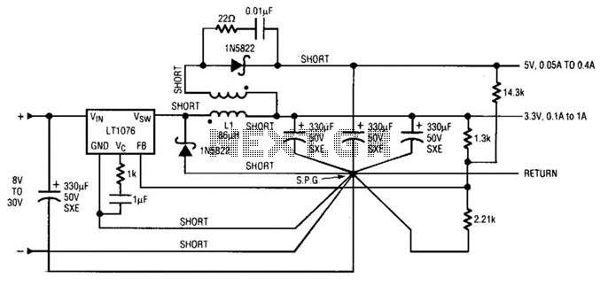
Input voltages can range from 8 V to 30 V. The load range for the 5 V output is from 0.05 A to 5 A, while the load range for the 3.3 V output is from 0.1 A to...
This circuit is designed to indicate the power output level of any audio amplifier. It is simple, portable, and displays three power levels that can be set to any desired value. For a standard HiFi stereo power amplifier, such...
This device is a successor to the PIC16C71 4-digit LED frequency counter and voltmeter. It omits some hard-to-find components from the previous version that have been out of production for some time. The earlier PIC16C71 has been replaced with...
When the preset is set to its maximum, the LED flashes approximately every half second. This flashing rate can be increased by using a larger capacitor value, for instance, changing from 10µF to 22µF will result in a flashing...

This is a design circuit for a UHF transmitter. The TV transmitter operates within the UHF frequency range of 470-580 MHz, specifically on channels 21-34. It can transmit signals over distances of 30-100 meters using a cable length of...