
Battery Self Discharge Indicator

The circuit designed for monitoring the self-discharge of lead-acid batteries incorporates a PNP transistor and a Zener diode to create a simple yet effective voltage monitoring system. The primary component, the PNP transistor (T1), acts as a switch that controls the LED indicator based on the battery's voltage level. The Zener diode (ZD) serves as a voltage reference, ensuring that the base of T1 remains sufficiently biased for conduction.
When the battery voltage is above 11.6 volts, the Zener diode conducts, allowing current to flow to the base of the PNP transistor. This keeps the transistor in the off state, preventing current from flowing through the LED, which remains unlit. However, as the battery discharges and the voltage drops below 11.6 volts, the Zener diode ceases to conduct. Consequently, the base of the PNP transistor receives a negative bias, turning it on and allowing current to flow through the LED, which lights up to signal that the battery needs charging.
A variable resistor (VR) is incorporated into the circuit to allow for fine-tuning of the threshold voltage at which the LED activates. This feature enables customization based on specific battery characteristics or user preferences, enhancing the circuit's versatility.
Overall, this circuit provides an efficient solution for monitoring lead-acid batteries during periods of inactivity, helping to prevent over-discharge and extend the battery's lifespan. The simplicity of the design, combined with the functionality of the components, makes it an ideal project for electronics enthusiasts and professionals alike.If the lead acid battery is not using for long time, self discharge takes place at the rate of 4 % per week at 27 degree. For example, a 125 Ah tubular battery self discharge at the rate of 5 Amps current per week if it is not in charge / discharge cycles.
This add on circuit can be used to detect the self discharge of the 12 volt lead acid battery below the safe level of 11. 6 volts. It is ideal to monitor the charge level in the battery, it the battery is not using for long period. The circuit uses only a few components and its working is simple. A PNP transistor T1 act as a switch to light the LED, if the battery voltage drops below the safe level. The base bias of T1 is controlled by a Zener diode ZD. Its rating is 10 volt 1 W. The Zener diodes usually requires 1. 6 volts excess than its rated value to enter into the Avalanche state . So, as long as the battery voltage is above 11. 6 (10+1. 6), Zener conducts and keeps the base of T1 high. Since T1 is a PNP transistor, it will not conduct till its base becomes negative. So LED remains dark. When the voltage in the battery reduces below 11 volts, Zener turns off and the base of T1 becomes negative.
T1 then conducts and LED lights. So the battery can be charged again to keep it in top condition. Preset VR can be used to set the exact point at which LED turns on. Be the first of your friends to get free diy electronics projects, circuits diagrams, hacks, mods, gadgets & gizmo automatically each time we publish. Your email address & privacy are safe with us ! 🔗 External reference
Related Circuits
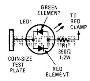
This circuit comprises a tri-color LED, a resistor, wire, and a coin-sized test plate. Two circuits must be constructed, one for each black clamp on a set of auto battery jumper cables. The circuits are installed inside the black...
The circuit has been designed for telephone apparatus to indicate an incoming call as it rings using an LED for visual indication. BC550, an NPN general-purpose transistor, is utilized in the design. The circuit operates by detecting the ringing voltage...
In the circuit below, a quad voltage comparator (LM339) is used as a simple bar graph meter to indicate the charge condition of a 12 volt, lead acid battery. A 5 volt reference voltage is connected to each of...

When light strikes the CDS cell, it activates the transistors, which in turn energizes the relay, causing it to latch. Pressing switch SI grounds the base of the 2N3565 transistor, thereby resetting the relay. Additionally, a 250 k potentiometer...
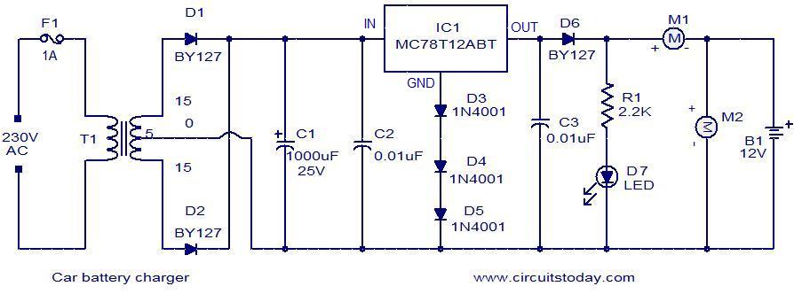
Below is a simple circuit designed for charging car batteries. This circuit includes the capability to monitor both the charging current and voltage. It utilizes the IC MC78T12ABT from Freescale, which is essentially a 7812 in a TO-3 package...
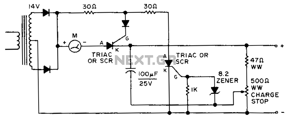
By adjusting the circuit with a 500-ohm resistor, the resistor is integrated into a fully charged battery system. The circuit described involves a 500-ohm resistor that plays a crucial role in regulating the operation of a fully charged battery system....