
Battery-Voltage Measuring Regulator

The circuit design incorporates a Texas Instruments TI43 precision shunt regulator, which is known for its stability and accuracy in voltage regulation applications. The TI43 operates by maintaining a constant output voltage, which serves as a reference point for measuring the battery voltage.
To facilitate the measurement process, the circuit includes an integrator/amplifier configuration that captures the voltage across the battery. The voltage-dependent charge and discharge time intervals are critical; they allow the circuit to respond accurately to changes in battery voltage. This is achieved by monitoring the time taken for the capacitor in the integrator circuit to charge and discharge, which varies based on the battery voltage level.
The output from the integrator/amplifier is then fed into the microprocessor, which requires a software routine to interpret the voltage levels. This routine should include algorithms to calculate the battery voltage based on the measured time intervals and the known characteristics of the TI43 shunt regulator. The software will likely involve analog-to-digital conversion processes, ensuring that the microprocessor can read the voltage levels accurately and make decisions based on the battery's state.
In summary, this circuit not only measures the battery voltage effectively but also integrates seamlessly with the microprocessor system, requiring careful software development to ensure accurate readings and appropriate responses to varying battery conditions. This circuit allows a microprocessor system to measure its own battery voltage. A Texas Instrument TI43 1 precision shunt regulator acts as a precision reference and integrator/amplifier, measuring its own supply via voltage-dependent charge/discharge time intervals. Notice that you must write a short control and voltage calculation software routine for your system.
Related Circuits
This device is designed to be a simple, inexpensive comparator intended for use in a solar cell power supply setup where a quick "too low" or "just right" voltage indicator is needed. The circuit consists of one 5V regulator,...
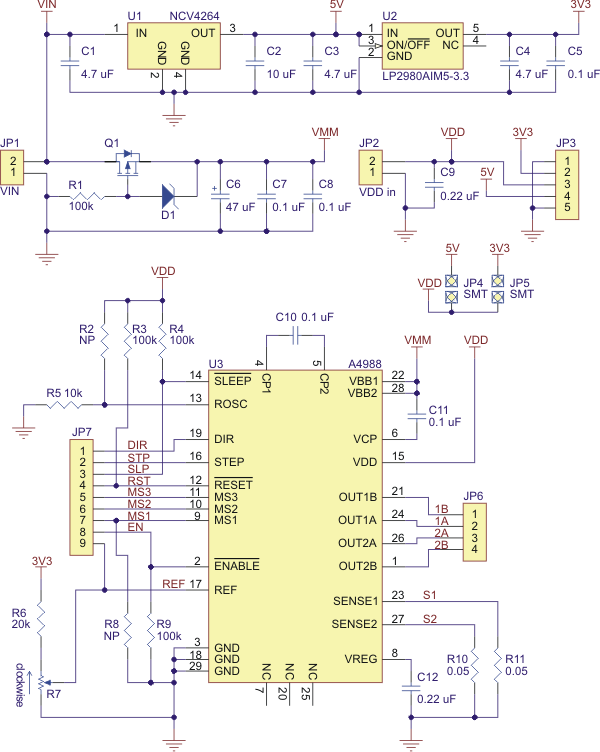
Best 1183 - A4988 Stepper Motor Driver Carrier with Voltage Regulator in Robot Italy. The A4988 stepper motor driver carrier with voltage regulators is a breakout board for Allegro's easy-to-use A4988 microstepping bipolar stepper motor driver. The board has...
The SIMD1 was enhanced in the Solar Regulator version which supplies a constant 2V after triggering and permits driving LEDs without using current limiting resistors with constant brightness. Note that you can use this Low Drop Out (LDO) linear...
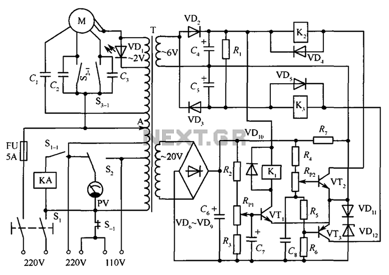
The circuit illustrated in the figure features an automatic voltage regulator (T) that utilizes a servo motor to ensure a constant output voltage. The transistors used are VT1 and VT2 (3DK9C, with a range of 65 to 85) and...
Often, there are instances where it becomes necessary to wind a coil for a project or to identify an unmarked coil found in a collection. To determine its inductance, an oscilloscope can be utilized. A resonant circuit can be...
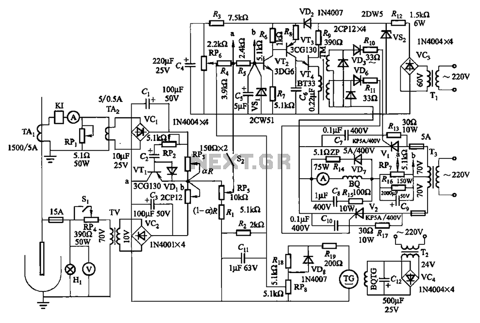
The circuit is illustrated in Figures 16-95 to 16-97. The electrode automatic adjuster demonstrates enhanced performance, featuring a high-accuracy, well-linear current output type bridge. Additionally, it incorporates a differential arc current negative feedback circuit (advanced) that allows for preemptive...