
Stepper Motor Driver Carrier with Voltage Regulator

The A4988 stepper motor driver carrier is designed for controlling bipolar stepper motors in a variety of applications, particularly in robotics and automation. The board integrates the A4988 microstepping driver, which allows for smooth motion and precise control of the motor. The inclusion of two voltage regulators—5 V and 3.3 V—facilitates the powering of both the motor and the logic circuitry from a single power source, streamlining the design process and reducing the number of components required.
Adjustable current limiting is a key feature of the A4988 driver, allowing users to set the maximum current supplied to the motor coils. This is crucial for preventing overheating and ensuring the longevity of the motor. Overcurrent protection further enhances the reliability of the system by shutting down the driver in the event of a fault condition, thereby safeguarding both the driver and the motor.
The A4988 supports five different microstepping resolutions, which include full step, half step, quarter step, eighth step, and sixteenth step. This flexibility enables users to select the appropriate resolution for their specific application, balancing torque and precision. The operating voltage range of 8 to 35 V allows for compatibility with a wide array of power supplies, making it versatile for different setups.
In summary, the A4988 stepper motor driver carrier is an efficient and user-friendly solution for controlling bipolar stepper motors, equipped with essential features such as voltage regulation, current limiting, and microstepping capabilities, making it suitable for a variety of robotic and automation projects.Best 1183 - A4988 Stepper Motor Driver Carrier with Voltage Regulator in Robot Italy The A4988 stepper motor driver carrier with voltage regulators is a breakout board for Allegro s easy-to-use A4988 microstepping bipolar stepper motor driver. The board has two voltage regulators (5 V and 3.3 V), eliminating the need for separate logic and motor supplies.
The driver features adjustable current limiting, overcurrent protection, and five different microstep resolutions. It operates from 8 35 V and can deliver up to 2 A per coil.. 🔗 External reference
Related Circuits
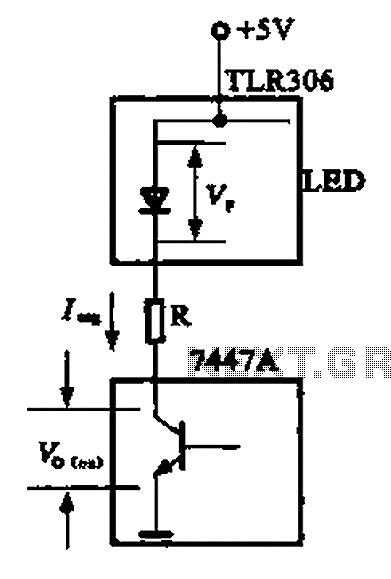
The circuit depicted is a large high-brightness LED driver designed to provide sufficient drive current, utilizing integrated circuits such as the 7447A or 74247. The digital display tube consists of eight light-emitting diodes, with seven dedicated to the digital...
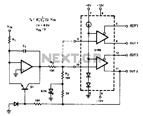
The D169 functions as a level detector, offering complementary outputs. An operational amplifier (op amp) is employed to integrate the input signal Vin, utilizing a time constant defined by the resistor R1 and capacitor C1. A negative input signal...
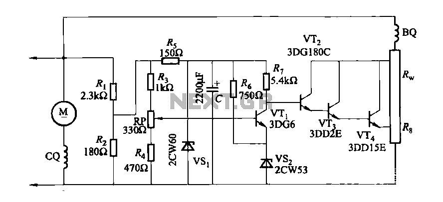
The DC generator automatic voltage regulator circuit is illustrated in Figure 7-53. This circuit is designed for a 40kW, 230V DC shunt complex machine, with a voltage change rate of up to 2.5 percent. In Figure 7-53, BQ represents...
To sense and control the current in stepping motors and other similar devices, a linear integrated circuit such as the L6506 can be utilized. This chip set enables the formation of a constant current output. The L6506 is a versatile...
The 555 IC is wired as an astable and the frequency is constant and independent of the duty cycle, as the total resistance (R charge + R discharge, notice the diode) is constant and equal to 22Kohm (giving a...
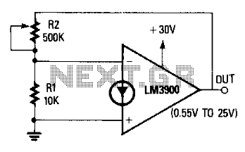
The non-inverting terminal of the operational amplifier (op-amp) is grounded, and the circuit utilizes the voltage at the inverting terminal as a reference. The voltage gain of the circuit is determined by the ratio of resistors R2 to R....