
Battery Watchdog Circuit

The circuit operates as a battery voltage monitoring and charging control system. The Zener diodes are selected based on their breakdown voltages, with one Zener diode (D1) set to trigger at a lower threshold of 11 V and the other (D2) at an upper threshold of 14 V. This creates a hysteresis effect that prevents rapid cycling of the charger on and off, ensuring stable operation.
When the battery voltage falls below 11 V, D1 becomes reverse-biased, which results in pin 3 of flip-flop IC2 transitioning to a high state. This transition activates the output of the flip-flop, which then drives the base of transistor Q1. Q1, when turned on, allows current to flow through K1, which represents the battery charger relay or control circuit. This connection initiates the charging process, thereby restoring the battery voltage.
On the other hand, when the battery reaches a voltage above 14 V, D2 becomes forward-biased. This condition causes the reset pin of flip-flop IC2 to be activated, which in turn resets the flip-flop and deactivates Q1. The deactivation of Q1 interrupts the current flow to K1, effectively disconnecting the battery charger from the circuit. This dual Zener diode configuration provides a reliable and efficient method for maintaining the battery within a safe operating voltage range, preventing overcharging and deep discharging, which can significantly extend the life of the battery.
Overall, this circuit design exemplifies a simple yet effective approach to battery management, utilizing common electronic components to achieve critical functionality in battery-operated systems. This circuit uses a pair of Zener diodes to monitor battery voltage of a 12-V battery. If below 11 V, 1)1 ceases to conduct, pin 3 of 102 goes high, setting FF IC2 turning on Ql, Kl, and the battery charger. At excess of 14-V battery voltage (full charge), D2 conducts, resetting FF IC2, and cutting off the battery charger.
Related Circuits
A common-base Colpitts oscillator utilizes a PNP transistor as the amplifying component. In this configuration, regenerative feedback is sourced from the tank circuit and directed to the emitter. The base bias is supplied by resistors RB and RF, while...
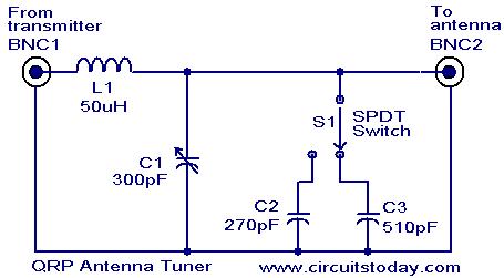
Low power (3 to 30 MHz) transmitters constructed by amateur radio operators are commonly referred to as QRP transmitters. A well-tuned antenna is essential for these transmitters; if the impedance is not properly matched, the output will be minimal...
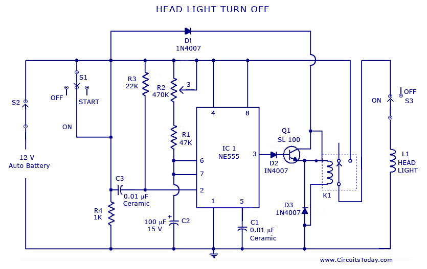
A circuit that can automatically turn off the headlights or lamps of a vehicle after a preset time. This light switching circuit is constructed using a 555 timer integrated circuit (IC). The described circuit utilizes the 555 timer IC in...
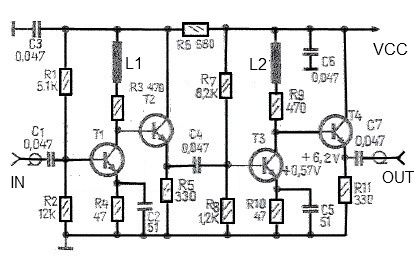
This antenna amplifier is effective for the frequency range of 35 kHz to 150 MHz. The circuit utilizes transistors and features a low 3 dB non-linearity along with a high gain of 43 dB. The input and output impedance...
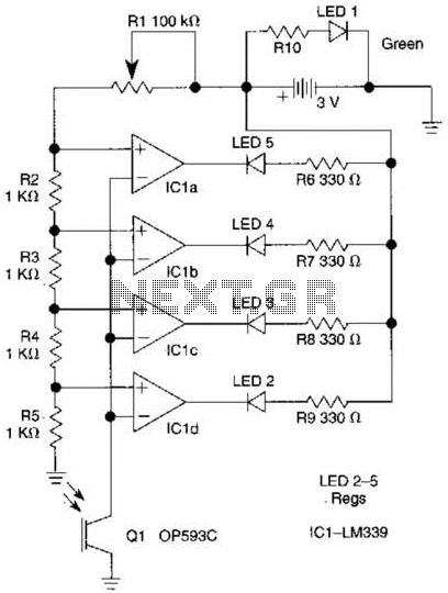
The outputs from the comparators will transition, in sequence, from high to low as the input voltage exceeds the reference voltage applied to each comparator. The output LEDs will activate sequentially as the voltage increases. The inverting inputs of...
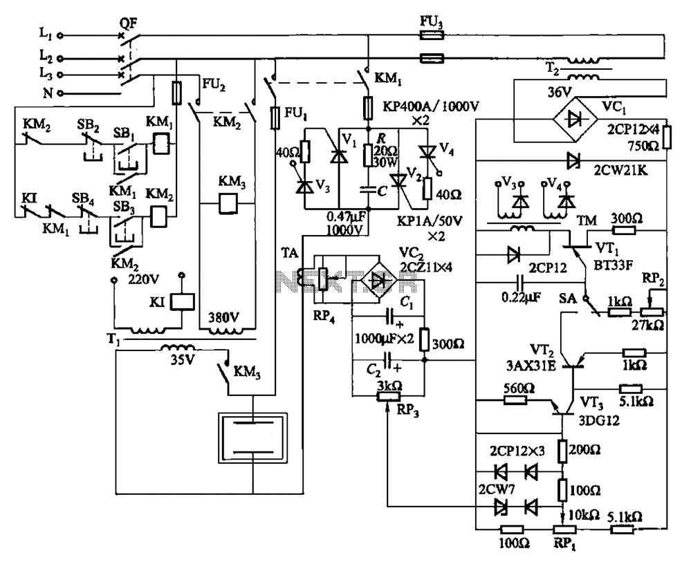
80 kW resistance salt bath furnace control circuit. The salt bath resistance furnace is a high-power device that employs fast start and temperature control technology to significantly save energy. The circuit includes a single-junction transistor (VTi) used as a...