
QRP antenna tuner circuit

The circuit for the QRP transmitter antenna matching system typically includes a tuner, which serves to adjust the impedance levels between the transmitter and the antenna. The tuner consists of a variable inductor (L1) and a variable capacitor (C1), which are critical components for achieving resonance at the desired frequency range of 3 to 30 MHz.
In the schematic, the transmitter output is fed into the tuner via a BNC connector (BNC1). The tuner then processes the signal and outputs it through another BNC connector (BNC2) to the antenna. The adjustment of L1 and C1 is crucial for maximizing the power transfer; this is performed by tuning these components while monitoring the output with a Standing Wave Ratio (SWR) meter, which indicates the efficiency of the power being radiated by the antenna.
Proper tuning ensures that the impedance seen by the transmitter matches the characteristic impedance of the antenna system, typically 50 ohms. If the SWR is low (ideally 1:1), it indicates a good match, allowing for maximum power transfer and efficient operation of the transmitter. If the SWR is high, it suggests a mismatch, which can lead to reduced power output and potential damage to the transmitter due to reflected power.
This circuit is particularly useful for amateur radio enthusiasts who aim to optimize their QRP operations, enabling effective communication over various distances while maintaining low power consumption.Low power ( 3 to 30 MHz) transmitters constructed by hams are generally called QRP`s. For such transmitters a well tuned antenna is a must. If the impedance is not properly matched there will be a little or no output. But if properly matched there will be great results. A circuit for matching the antenna properly with the transmitter id given below. The output of the transmitter is given to the input of the tuner( connector BNC1). The output of the tuner(connector BNC2) must be connected to antenna. Then adjust the L1 and C1 to obtain the maximum transmission power. The transmission power can be checked using a SWR meter. 🔗 External reference
Related Circuits
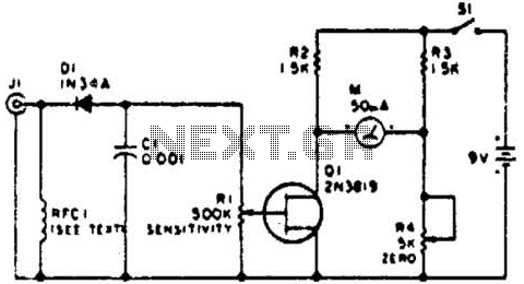
This circuit employs a FET as a DC amplifier within a bridge configuration. Resistor R4 is adjusted for meter nulling with switch J1 short-circuited. Any surplus 50-mA meter can be utilized in this circuit. RFC1 represents a suitable RF...

The circuit depicted in Figure 3-187 illustrates the operation of an auto step-down transformer (ZQB). Upon activation, the ZQB transformer initiates a sequence that allows the motor to gradually increase its speed. After a predetermined delay, the ZQB ceases...

Comprehensive information about RF Probe Circuits is available. Users can learn about and download RF Probe Circuit designs online. RF Probe Circuits are essential tools for testing and analyzing radio frequency signals in various applications, including telecommunications, broadcasting, and electronic...

Any number of normally-open switches may be utilized. Install "tilt" switches that close when the steering is moved or when the bike is lifted off its side-stand or pushed forward off its centre-stand. Employ micro-switches to secure removable panels...

The LT3755 is utilized for high-side current sensing in LED strings, enabling flexible programming and control. It supports a PWM input that allows for a dimming ratio of up to 3000:1, while the CTRL input offers additional analog dimming...

It consists of a 4047 low-power monostable/astable multivibrator, IC1, used in the astable mode to provide the timing pulses to control the flash rate of the LEDs. To accomplish the astable mode, pins 4, 5, 6, and 14 are...