
BC 547 Transistor For Garage Alarm Sensor

The BC 547 transistor is a popular NPN bipolar junction transistor (BJT) that is frequently used in various electronic applications, including alarm systems. In this specific garage alarm sensor circuit, the BC 547 acts as a signal amplifier and switch, allowing for the detection of unauthorized access.
The circuit typically consists of several key components: the BC 547 transistor, resistors, a piezo buzzer or alarm, and a sensor element, which could be a motion detector or a magnetic reed switch. The sensor is responsible for detecting movement or the opening of a garage door. When the sensor is triggered, it sends a small current to the base of the BC 547 transistor.
This small current enables the transistor to conduct, allowing a larger current to flow from the collector to the emitter. As a result, the connected alarm (such as a piezo buzzer) is activated, emitting a sound to alert the homeowner of a potential intrusion.
Resistors in the circuit are used to limit the current flowing to the base of the transistor, ensuring that it operates within safe limits and preventing damage to the components. Additionally, a power supply is necessary to provide the operating voltage for the circuit, typically ranging from 5V to 12V, depending on the specific design requirements.
Overall, the BC 547 transistor garage alarm sensor circuit is an effective and straightforward solution for enhancing security in a garage environment, offering reliable performance with minimal complexity.The following circuit shows about BC 547 Transistor For Garage Alarm Sensor Circuit Diagram. Features: simple single-zone burglar alarm circuit, .. 🔗 External reference
Related Circuits
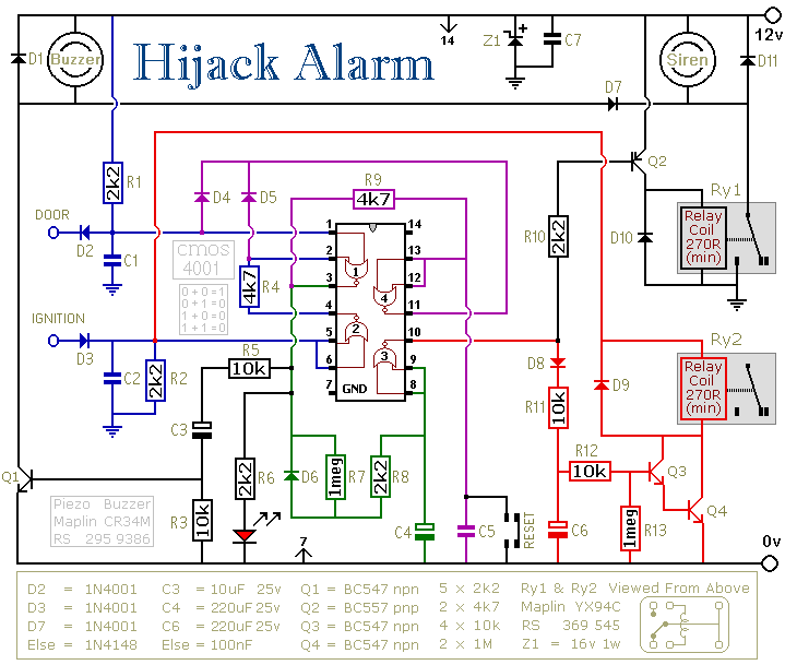
The first circuit was designed for the situation where a hijacker forces the driver from the vehicle. If a door is opened while the ignition is switched on - the circuit will trip. After a few minutes delay -...
This circuit operates with a 12V supply connected to a motor, utilizing transistors TIP 142 and TIP 147. Each transistor is controlled by a high (5V) or low (0V) signal through a 1kΩ resistor. The diodes used in the...
The Proteus files can be found. Recently, four pairs of ultrasound MA40S4 receivers/transmitters from Murata were purchased. They function as a pair of ultrasound microphones and speakers. The objective is to build a simple homemade ultrasound sensor for detecting...
This digital alarm speedometer circuit allows for the measurement of the acceleration of any moving object, particularly cars and other vehicles. The acceleration is displayed in kilometers per hour (KPH) with a three-digit display. The system operates using laser...
This is an ultrasonic motion detector circuit with high movement sensitivity. It can detect even minor air movements, such as hot air rising or wind blowing, when the trimpot is adjusted to a sensitive position. The transmitter emits a...
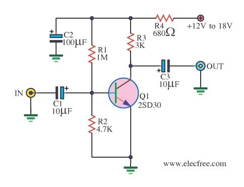
When there is a need to amplify audio signals from various sources before they reach a custom amplifier, a preamplifier (or preamp) is typically employed. This document suggests a specific circuit that is interesting due to its use of...