
BCI Filter

The AM broadcast signal eliminator circuit is designed to effectively filter out unwanted AM signals, allowing for more accurate antenna measurements. The series resonant circuit comprising L1 and capacitors C1, C2, and C3 is critical in shunting the undesired signals to ground. The selected inductor, L1, with approximately 50 microhenries, is constructed using a specific number of turns of wire, which influences the inductance value and the circuit's overall performance. The variable capacitors C1 and C5 enable fine-tuning of the resonant frequency, allowing the user to adapt the circuit to various operational frequencies of different antennas.
The inclusion of capacitors C2 and C3, which can be combined to achieve a higher total capacitance, adds flexibility to the circuit design. The use of an aluminum enclosure for housing the circuit is beneficial due to its ease of modification and durability, which is essential for practical applications.
The tuning process involves connecting the circuit to an Antenna Analyzer, which is a crucial step in ensuring that the circuit performs as intended. By adjusting C1 to achieve a minimum SWR reading, the user can effectively nullify the AM broadcast signal, allowing for clearer measurements. The subsequent adjustment of C5 ensures that the output impedance is matched to 50 ohms, which is standard for most RF applications, thereby optimizing performance.
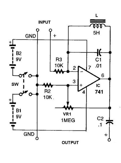
Overall, this circuit serves as a valuable tool for amateur radio operators and anyone involved in antenna design and testing, providing a means to eliminate interference from AM broadcast signals and enhance measurement accuracy.Designing and building an AM Broadcast Sucker-outer. The undesired AM broadcast signal is shunted to ground with a series resonant circuit consisting of L1 and C1, C2, and C3. At the HF frequencies, this series circuit will look like an inductor from Input to ground, so I put a variable capacitor (various combinations of C4 and C5) across the series resonant circuit to create a parallel resonant circuit at the
operating frequency of the antenna being designed. The entire circuit is built in a large outlet box, but I`d recommend using an aluminum enclosure from Radio Shack because it`s much easier to drill holes in. L1 is about 50 microhenries (not critical), which is 60 turns of #30 wire on a piece of PVC tubing that`s 1 inch OD, by 2 inches long.
C1 and C5 are 15 - 365pf air variables. C2 and C3 can be combined for a total of 800pf. C4 is switched in to cover 15m and 10m. Layout is not critical, but short lead lengths are always a good idea. This was a prototype that worked, so I never bothered to clean up the design. I think replacing S1 with a pair of toggle switches might be a good improvement. Connect the tunable filter Input to your Antenna Analyzer, and the Output of the filter to the antenna. Tune the analyzer to the operating frequency of the antenna, and adjust C1 for a minimum "SWR" reading.
In doing this, you are nulling the AM broadcast signal. Now put a 50 ohm load on the Output connector of the filter, and adjust C5 for 50 ohms with zero reactance. You are now ready to make antenna measurements without that pesky AM Broadcast signal driving your Antenna Analyzer crazy.
If you have any questions or suggestions for improvement of this circuit, please let me know. This was a project that wasn`t on the list when I wanted to tune my 40m Inverted Vee, and I didn`t stop to make improvements. 🔗 External reference
Related Circuits

This is a third-order low pass filter with a corner frequency of 20 kHz, which is twice the auto-zero clock frequency. The third-order low pass filter is designed to attenuate high-frequency signals while allowing low-frequency signals to pass through...
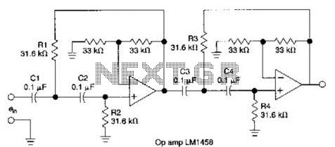
This circuit, which utilizes an LM1458 or a similar operational amplifier, functions as a fourth-order high-pass filter with a roll-off rate of 24 dB per octave. The resistor values Rx/R2 and RJRV can be adjusted to accommodate different cutoff...
The above diagram is a standard low-pass telephone line filter (L1,C1,L3,C2). L2 and L4 are needed since we're dealing with the 'Tip' and 'Ring' of a phone line which may carry up to 90VAC. Additional info can be found...
The RF amplifier is similar to the one used in the 2.5 MHz amplifier. At a frequency of 10 MHz, the capacitances of a power MOSFET become significant. Noiseless feedback using transformers is no longer straightforward. Intermodulation and overtones...
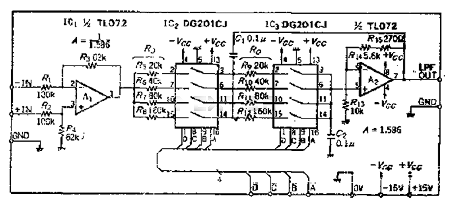
The circuit primarily consists of two Butterworth filters, designed to create a feedback amplifier with a gain of approximately 0.707. It features a differential input amplifier, where one input is grounded, resulting in a single input terminal. The attenuation...
This circuit will filter out interference signals and ensure that the signal received from the Morse code station stands out. The described circuit functions as a signal processing system specifically designed to enhance the clarity of Morse code transmissions by...