
Simple Ham Radio Circuit Audio Filter With 741 IC

The described circuit functions as a signal processing system specifically designed to enhance the clarity of Morse code transmissions by minimizing the impact of unwanted interference. The primary components of this circuit typically include a bandpass filter, an amplifier, and a demodulator.
The bandpass filter is crucial in allowing only the desired frequency range associated with Morse code signals to pass through while attenuating frequencies outside this range. This is essential for isolating the Morse code signal from background noise and other unwanted signals.
Following the filtering stage, the amplified signal is directed to an amplifier. The amplifier boosts the filtered signal to a level suitable for further processing. This stage is vital in ensuring that the signal strength is sufficient for the demodulation process, which converts the modulated Morse code signal back into a readable format.
The demodulator then interprets the amplified Morse code signal, converting it into a format that can be understood by the receiving equipment or operator. This may involve translating the signal into audio tones or visual representations, allowing for effective communication.
In summary, this circuit is designed to enhance the reception of Morse code signals by filtering out noise and interference, amplifying the desired signals, and processing them for clear communication. This comprehensive approach ensures reliable Morse code transmission and reception in various operational conditions.This circuit will help to filter out the interference signal and ensure that the signal received from the Morse code station stand out. The .. 🔗 External reference
Related Circuits
The following circuit illustrates an Ultrasonic Sensor Circuit Diagram. This circuit is based on the MAX232 IC. Features include a quiescent current of 150mA. The Ultrasonic Sensor Circuit utilizes the MAX232 integrated circuit, which is primarily designed for converting signals...
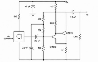
Preamp circuits are used in front of an RF oscillator to create an RF transmitter that is highly sensitive to sound. A microphone preamp must provide stable gain. Preamp circuits play a crucial role in the functioning of RF transmitters...
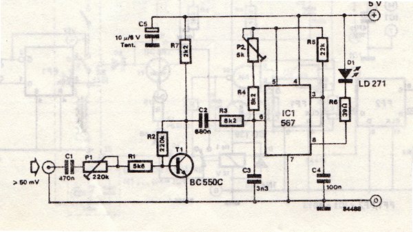
The transmitter is equipped with an LM567 tone decoder circuit. An audio signal (at least 50 mV peak-to-peak) is amplified with a transistor (T1) and then used to modulate IC1. The infrared transmitter frequency is adjusted with potentiometer P2...
The recommendation regarding the existing phono connector is to maintain its current configuration without making significant alterations. The procedure involves replacing the electrolytic and paper capacitors, adding a three-wire line cord, and utilizing the radio in its original state....
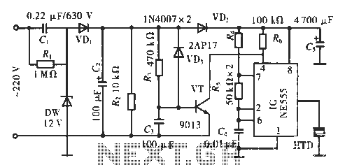
The circuit utilizes a 555 integrated circuit (IC). When an incoming call is received, 220 V AC is stepped down through resistor R1, followed by rectification using diode VD1. A voltage regulator (DW) is employed, and capacitor C2 is...
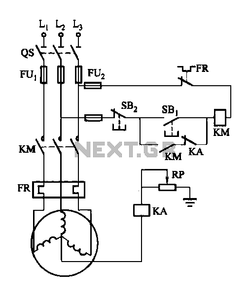
A potentiometer (RP) is utilized for adjusting the operating voltage of the relay (KA) to ensure that the motor operates normally, especially when the relay (KA) does not function reliably during the action phase. The circuit involves a potentiometer...