
Windspeed Indicator Circuit With LM7805 IC

The wind speed indicator circuit is designed to measure and display wind speed in a user-friendly manner. The core of the circuit is the LM7805 voltage regulator, which ensures that the circuit receives a stable 5 VDC power supply. This is critical for the accurate operation of the sensing and display components.
The circuit typically incorporates a wind speed sensor, such as a small anemometer, which converts wind speed into an electrical signal. This sensor is connected to an analog-to-digital converter (ADC) if a digital display is utilized, allowing the microcontroller to interpret the sensor's output. The microcontroller processes the input data and drives a display, which may be an LCD or LED screen, to show the wind speed in real-time.
The 9 VDC supply serves as the input voltage for the LM7805 regulator, which steps down the voltage to 5 VDC. This regulator is chosen for its simplicity and reliability, making it suitable for various applications in electronic circuits. Additional components may include resistors, capacitors, and diodes, which help stabilize the voltage and protect the circuit from potential damage due to voltage spikes.
Overall, the wind speed indicator circuit is a practical application of basic electronic principles, combining sensors, microcontrollers, and voltage regulation to provide a functional and informative device for measuring wind speed.the following circuit shows about Windspeed Indicator Circuit. Features: down to a constant 5 VDC by the LM7805 voltage regulator, 9 VDC supply .. 🔗 External reference
Related Circuits
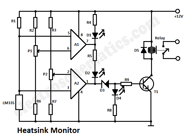
This heatsink temperature monitor circuit uses three LEDs to signal when the temperature exceeds two boundary levels. When the heatsink temperature is below 50 degrees... This heatsink temperature monitor circuit is designed to provide visual indications of temperature levels using...
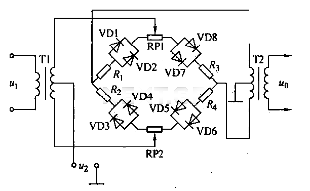
An AM diode ring circuit consists of four diodes arranged in a ring configuration, commonly referred to as a diode ring modulator circuit. This circuit offers significant advantages due to the characteristics of the diodes and the use of...
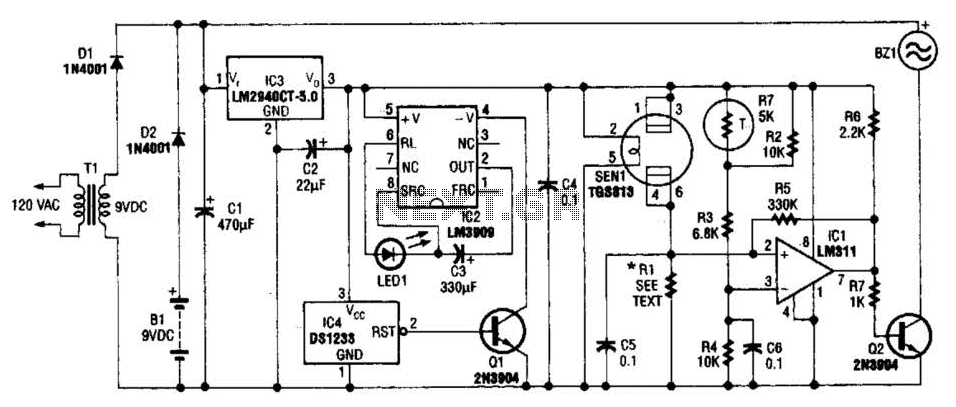
The gas sensor primarily consists of tin dioxide mounted on a ceramic substrate. The sensor's resistance changes based on the concentration of reducing gases present in the air. The depicted circuit is effective for detecting hazardous levels of combustible...

Inverters U1a and U1b are connected in a simple RC oscillator circuit. The frequency is determined by the values of R1, C1, C2, and the internal characteristics of the integrated circuit. As long as the circuit is oscillating, a...
The Reaction Capability Tester is utilized to assess and enhance an individual's quick-response abilities. It features various designs, with the depicted model comprising a CD4017 decimal counter and a light-emitting diode (LED). The construction of the Reaction Capability Tester...
The timing doorbell circuit utilizing the CW9300 is depicted in the provided diagram. This circuit features a timing function that, upon pressing the button, plays music for a specified duration. If the button is pressed again immediately after releasing...