
Low current consumption lamp flasher

Using the indicated component values, the total period is around 0.55 seconds, with a duty cycle of approximately 7% and a mean battery current, including the Vb divider, of about 1.5 mA.
The circuit described is a simple astable multivibrator configuration that utilizes transistors for generating a square wave output. The choice of transistors is flexible, allowing for various types, which contributes to the circuit's cost-effectiveness. The self-starting nature of the circuit is a significant advantage, ensuring that it begins oscillation without external triggering.
The voltage divider for Vb is critical in determining the base current for Tr3, which affects the oscillation frequency. When Vb is supplied from a fixed voltage source, the circuit's performance becomes sensitive to battery voltage levels, leading to slower flashing as the battery discharges. This behavior should be considered when designing for applications where battery life is a concern.
Resistor R4 plays a vital role in controlling the initial charging current of capacitor C1, which influences the timing characteristics of the circuit. The relationship between R2 and R4, particularly when they are set to equal values, simplifies the design process and allows for predictable timing intervals. The calculation of R2 as R6R7 / (R6 + R7) indicates the importance of selecting appropriate resistor values to achieve the desired timing characteristics.
The timing of the circuit is dictated by the capacitance of C1 and the resistance values of R2 and R1. The on-time and off-time calculations provide a framework for tuning the circuit to achieve specific operational requirements. The resulting period of 0.55 seconds and duty cycle of 7% suggest that this circuit is suitable for low-power applications, where minimal current draw is essential.
Overall, the described circuit is a reliable and efficient solution for generating periodic signals, with flexibility in component selection and straightforward design principles.The circuit is economical in components, and will work with virtually any transistors and is reliably self-starting. The voltage Vb can be taken from a divider, as shown at the right. If taken from a fixed source, flashing becomes slower as battery voltage falls. The lowest drive current into the base of Tr3 is about (Vb—0,6 V)/(R2 + R4). Resistor R4 limits the initial current from Cl and, as shown, R2 and R4 can be roughly equal when a divider is used for Vb.
Resistor R2 equals R6R7/(R6 + R7). With the voltages shown, and with R2 = R4, the on-time is about 1.1 C1R2 and the off-time about 0.28 C1R1. Using the component values shown the period is about 0.55 sec. with a duty cycle of about 7% and a mean battery current including the Vb divider, about 1.5 mA.
Related Circuits

The circuit regulates the RMS output voltage across a load, specifically a projection lamp, to 100 volts ±2% for input voltages ranging from 105 to 250 volts AC. This regulation is achieved by indirectly sensing the light output of...
A resistance temperature sensor (RTD, resistive temperature device) is available in two types: NTC (negative temperature coefficient) and PTC (positive temperature coefficient). Resistance Temperature Detectors (RTDs) are essential components in temperature measurement systems. They operate on the principle that the...
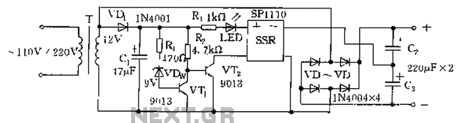
The circuit is automatically converted to a low-voltage configuration. A 220V AC supply is stepped down by transformer T. After this, the breakdown voltage of diode VDw causes transistors VT1 and VT2 to turn off, resulting in the solid-state...

This is a simple and effective LED-based night lamp circuit that can be powered directly from a 230V mains supply. The circuit uses a total of 24 white LEDs and produces an output of approximately 15W. The resistor R1...
Connect a 12V fan to this circuit that consumes 70mA (0.07A), ensuring the circuit can supply at least that amount of current. There appears to be a misunderstanding regarding the analysis. The voltage drop across the resistor equals the...
The Ai. A2 series operates with a telephone line, where sound anomalies or off-hook currents activate a light within an arc tube, which in turn triggers a photosensitive MOSFET. This process involves a saturated conduction base voltage that sends...