
Beeper driver with 555

The circuit described utilizes two 555 timer integrated circuits (ICs) configured in astable mode to generate a periodic "beep-beep" sound characteristic of a pager. The first 555 timer (IC1) operates as an oscillator, producing a square wave output at approximately 1 Hz. This output serves as the trigger for the second 555 timer (IC2), which is also configured in astable mode but operates at a higher frequency to generate the audible tone.
IC1's output frequency is determined by the resistor and capacitor values connected to it, particularly R1, R2, and C1. The timing components can be adjusted to change the frequency of the oscillation, effectively controlling how often IC2 is activated. The variable resistor VR1 allows for fine-tuning of this frequency, enabling the user to adjust the rate at which the second IC is turned ON and OFF.
IC2's output frequency, which produces the tone of the final sound, is controlled by its own timing components (R3, R4, and C2). The variable resistor VR2 provides the ability to modify the tone of the output sound, allowing for a range of audible frequencies to be generated. This flexibility is essential for customizing the sound output to meet specific requirements or preferences.
For applications where space or component count is a concern, a piezoelectric buzzer can be used in place of IC2. This substitution simplifies the circuit by eliminating the need for the second 555 timer and its associated components. However, it is important to note that while a piezoelectric buzzer is more compact, it typically produces a quieter sound and lacks the ability to vary tone as effectively as a speaker connected to IC2. Thus, the choice between using a second 555 timer or a piezoelectric buzzer depends on the desired sound characteristics and application requirements.This circuit produces the sound of a beeper like the one in pagers which produces a "beep-beep" sound. Basically the circuit consists of a 555 timer oscillator which is turned ON and OFF periodically. The first IC(left) oscillates at about 1Hz. The second IC is turned ON and OFF by the first IC. The first IC determines how fast the second IC is turned ON/OFF and second IC determines the tone of the final output.
By varying the VR1, the changeover rate can be adjusted. By varying VR2 the tone can be adjusted. If you know something about electronics, you can try replacing the 2nd 555 IC circuit with a piezoelectric buzzer. This saves one IC and associated components but the buzzer cannot give a loud sound as the speaker and also its tone cannot be varied.
🔗 External reference
Related Circuits
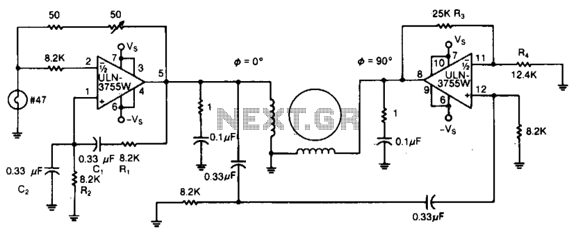
Due to its high amplification factor and integrated power-output stage, an integrated power operational amplifier serves as an effective driver for AC motors. One operational amplifier can be configured as an oscillator to generate the necessary AC signal. The...
The following circuit illustrates an Ultrasonic Sensor Switch circuit diagram. This circuit is based on the 555 Timer IC for the Ultrasonic Transmitter. The Ultrasonic Sensor Switch circuit utilizes a 555 Timer IC configured in astable mode to generate ultrasonic...
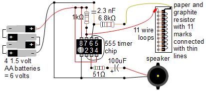
A simple music instrument/keyboard is created using a 555 timer chip circuit, a piece of paper, and a pencil. The project includes a more advanced automatic music player that utilizes a playing head and a long sheet of paper...
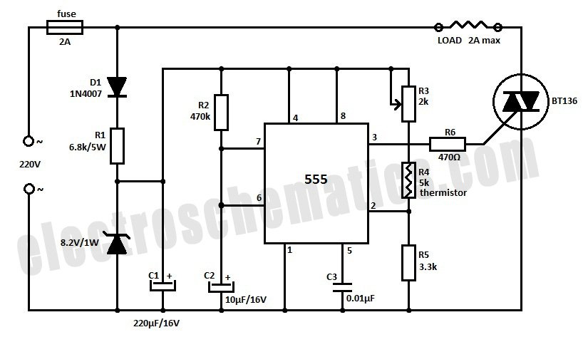
Construct a temperature controller circuit using the 555 integrated circuit (IC) in combination with a thermistor resistor divider. The benefit of this design is that it does not require a well-regulated power supply. The resistor divider network comprises an...
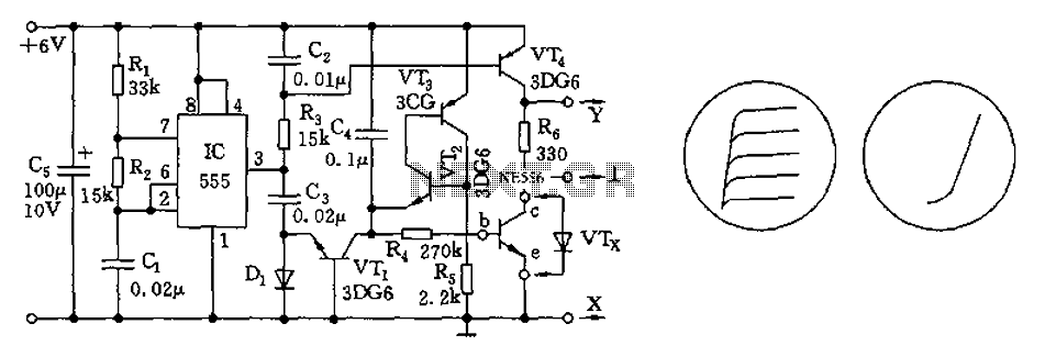
The transistor characteristic curve tracer circuit depicted in Figure 555 illustrates the characteristics of a transistor. It utilizes two voltages: a step wave applied to the base (b) to generate different base currents (Ib), and a sawtooth waveform at...
A drink mixer inspired by BAR2D2 utilizes a gravity-fed pump that operates on a 9V battery. The circuit incorporates a 555 timer to control the duration of the pump's operation. When connected directly to the battery, the pump functions...