
Beeping Down Counter Circuit

The schematic represents a well-structured electronic circuit that incorporates various components to achieve its functionality. Starting from the left, the state machine utilizes four NOR gates, enabling a three-state operation that facilitates transitions between set and start conditions based on user input. The countdown mechanism is initiated when the countdown value reaches zero, prompting the system to enter the 'trigger' state, which is crucial for the operation of the timer.
The use of decade counters is a strategic choice, as these components are configured to load a preset value of 25 when the set state is engaged. The outputs from the decade counters are then fed directly into the 4511 LED drivers, which are responsible for converting the binary output from the counters into a format suitable for driving the common-cathode 7-segment displays.
The integration of the 556 timer, which contains two independent 555 timer circuits, enhances the functionality of the schematic. One timer serves as the primary clock, emitting a frequency around 1 Hz, which is essential for timing applications. The second timer, configured to generate a sound frequency between 2-5 kHz, adds an auditory signal to the system, providing feedback to the user during operation.
It is important to note that the circuit is specifically designed for common-cathode 7-segment displays. This design choice necessitates careful consideration of the connection and configuration of the display components to ensure proper functionality. While the schematic indicates a single resistor connected between the common cathode pin and ground, it is advisable to incorporate individual resistors for each of the A-G inputs to limit current and protect the display from potential damage. This adjustment would enhance the reliability and longevity of the circuit in practical applications.The schematic for this project isn`t too, too bad to look at even though it`s not the best drawing/layout for a schematic that I`ve ever done. The basic flow is from left to right. Left side is the state machine, then the 555 timers, then counter circuitry and finally the 7 segment LED output circuitry.
The theory section explained this already a little bit, but the 4 NOR gates will act like a 3 state machine, with the buttons triggering between set and start states and the count down value of 00 moving the system to the `trigger` state. The decade counters are hardwired to load the value of `25` into the system when the set state is activated.
The outputs from these counters go directly into the 4511 LED drivers to set the count value on the display. The 556 IC appears as two 555 timers in the circuit. As discussed before one is used as a master or system clock at about 1 Hz and the other is used for generating the 2-5 KHz beep sound.
This system is made for common-cathode 7 segment displays, so be sure that`s what you`ve got. Similarly, it would be wiser to add resisters before the A-G inputs, but I got lazy and added a single resistor between the common cathode pin and ground. 🔗 External reference
Related Circuits
This circuit blanks the CRT starting just before retrace begins. Since the CRT sits at a -1200 volt potential, the blanking circuit must also be based at -1200 volts. Note the capacitors, C40, C41, and C43 which allow the...
This circuit is designed to detect the approximate percentage of salt in a liquid. After careful calibration, it can provide a quick, rough indication of salt content in liquid foods for dietary purposes. The operational amplifier IC1A is configured...
The circuit illustrated in the figure depicts an automatic bathroom light switch system. When the door is opened, the light is activated, illuminating the space. Conversely, when the door is opened again, the light turns off. The circuit comprises...
The circuit under discussion is a four-siren sound generator utilizing the UM3561 integrated circuit (IC), which is a low-power CMOS device. Four distinct sounds can be generated by activating switches S1, S2, and S3. This circuit is versatile and...
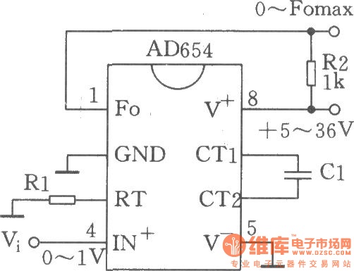
The circuit depicted is a low-cost voltage frequency converter (VFC) utilizing the AD654 component. By connecting the required components, Rl and Cl, as shown in the figure, a functional VFC application circuit can be established. The supply voltage can...
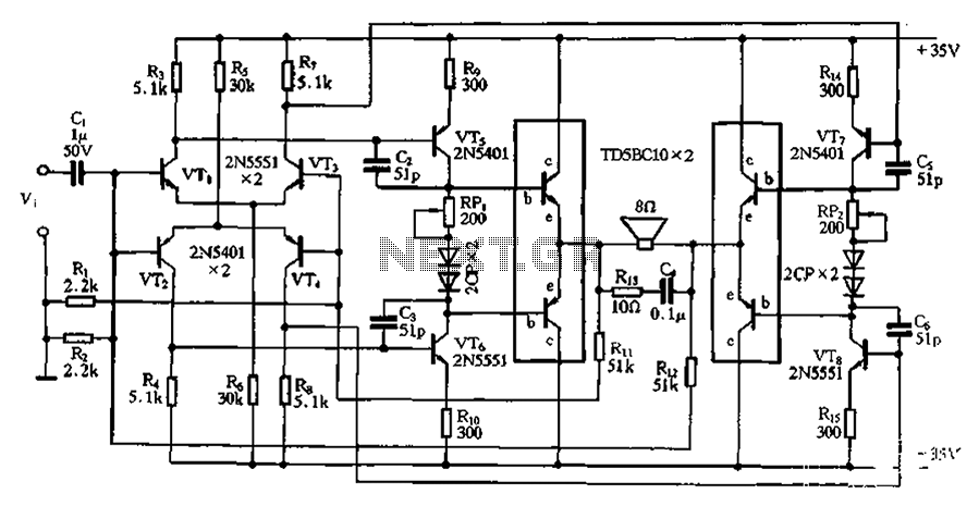
The bridge is a low-frequency push-pull power amplifier circuit with a simple structure, capable of delivering an output power of up to 1W. It can be utilized as an external amplifier for devices such as Walkmans, phones, doorbells, alarms,...