
Bell circuit with two 555 timers

The circuit operates using two 555 timer ICs configured in astable mode, which generates a continuous square wave output. The frequency of oscillation is determined by the timing components, specifically the resistors R1, R2, and the capacitors C1 and C2. For optimal performance, it is crucial that the capacitors C1 and C2 have closely matched values, as any significant difference may lead to uneven frequency outputs and affect the overall sound quality of the bell.
Resistors R1 and R2 are used to set the charge and discharge times of the capacitors, which in turn dictate the frequency of the output signal. Fine-tuning of the frequency can be accomplished by adjusting the values of R1 and R2, allowing for precise control over the pitch of the bell sound. The decay time of the generated tone is influenced by resistor R3, which controls how quickly the output signal diminishes after the initial activation of the circuit.
In this configuration, the output from the second 555 timer can be connected to a speaker or a piezo buzzer, producing the characteristic bell sound when the circuit is powered. The design can be further enhanced by adding additional components such as diodes for protection, or variable resistors for more extensive tuning capabilities. Proper layout and component selection are essential to ensure the stability and reliability of the circuit during operation.This simple Bell circuit uses two 555 timers. The frequency is controlled by the capacitors that must be preserved almost identical in value to each other for best results. Fine tuning is done with R1 and R2. The decay time is controlled by R3.
Related Circuits
This simple circuit combines two or more audio channels into a single channel (for example, converting stereo to mono). The circuit is capable of mixing any number of channels and operates with minimal power consumption. While the schematic illustrates...

A very useful talk-over circuit that can be utilized in radio stations, clubs, or any location where speaking over music is desired without the need for adjusting a potentiometer. The talk-over circuit is designed to automatically reduce the volume of...

Caution! This strobe light circuit operates on 220V, making measurements and experiments extremely hazardous, even after disconnecting it from the mains. The strobe light circuit is designed to produce high-intensity flashes of light at specified intervals. It typically consists...
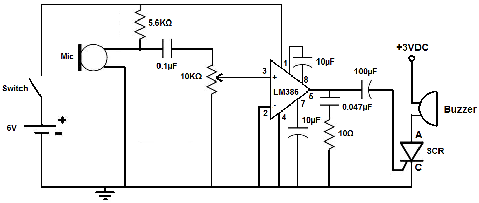
This circuit is designed to activate an alarm when it detects sound above a specified threshold. The alarm serves as a notification for any sound in areas that are typically quiet, such as quiet zones. Under normal quiet conditions,...

There have been several requests for a quiz circuit, leading to the development of a design featuring four inputs that can be easily modified. This circuit employs four integrated circuits (ICs) and includes four input circuits with independent outputs,...

The following circuit illustrates a basic monostable multivibrator, which is based on the 555 Timer IC. Key features include pin 4 functioning as the RESET pin, with the time period defined by the equation t = R1 x C1. The...