
Talk Over Circuit

The talk-over circuit is designed to automatically reduce the volume of background music when a microphone input is detected, allowing for clear communication without manual volume adjustments. This circuit typically employs a compressor or an automatic gain control (AGC) mechanism to achieve the desired effect.
The basic components of a talk-over circuit include a microphone preamplifier, a comparator, and a variable resistor or digital control for the music signal. The microphone preamplifier amplifies the audio signal from the microphone, ensuring that it is strong enough to trigger the subsequent components.
The comparator monitors the amplitude of the microphone signal relative to the music signal. When the microphone signal exceeds a certain threshold, the comparator sends a control signal to reduce the music volume. This can be achieved by using a voltage-controlled amplifier (VCA) or a relay that adjusts the music signal path.
The circuit may also incorporate additional features such as adjustable sensitivity and response time to fine-tune the operation according to the specific application. For instance, a longer response time can create a smoother transition between music and speech, while adjustable sensitivity allows for customization based on the ambient noise levels.
Power supply considerations are also important, as the circuit may require a stable voltage source to function correctly. It is common to use a dual power supply configuration to accommodate both the analog and digital components of the circuit.
In summary, the talk-over circuit is an essential tool for environments where clear audio communication is necessary over background music, providing an automated solution that enhances user experience without manual intervention.A very usefull talk over circuit which you can use in your radio stations, club or anywhere you want to speak over music without any movement of potentiome.. 🔗 External reference
Related Circuits
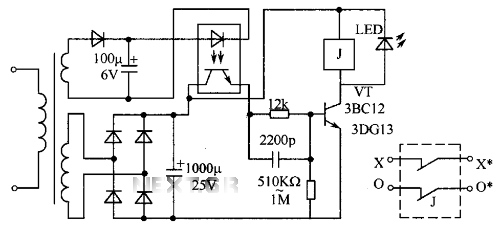
The circuit protection mechanism utilizes optocouplers for on-off control. Under normal voltage conditions, the output from the optocouplers is minimal, and the VT transistor operates in reverse bias. However, if the circuit voltage increases due to reasons such as...
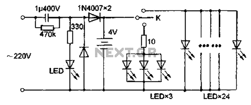
The circuit diagram depicted in Figure 5 illustrates a system for charging a lead-acid battery using 220V AC power. The circuit employs a capacitor, buck converter, and diode rectifier for this purpose. A red LED indicates the charging status....
With this circuit we can create a altered sound of siren. The oscillator IC1a-b is constituted by two gates NAND, oscillating in very low frequency. This oscillation drive the IC2, that is a electronic switch, which opens and closes...
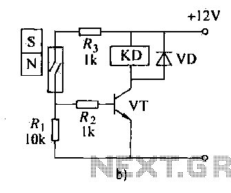
The automatic weapon features a magnetic switch circuit that is simple, reliable, has a low failure rate, and offers good versatility. It can be used to output performance or convert mechanical displacement. The circuit diagram utilizes a Hall switch...
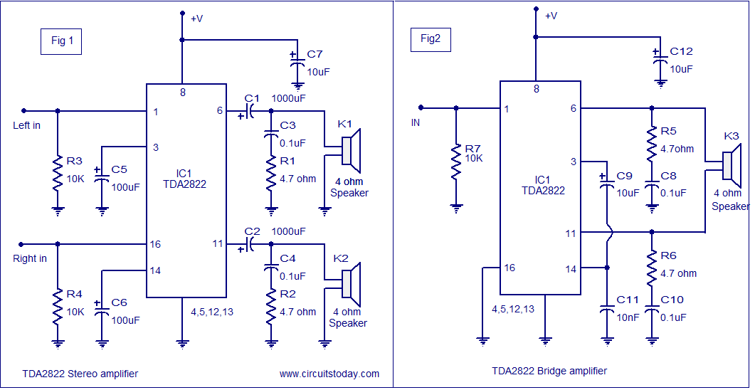
The TDA2822 audio amplifier circuit provides 1.35W output into a 4-ohm speaker when powered by a 6V supply. It supports both bridge and stereo modes and operates within a supply voltage range of 3V to 15V, making it suitable...
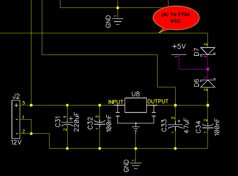
When only the voltage regulator (VR) supplies power to the circuit, the microcontroller unit (MCU) will receive power from the +5V bus, while the FTDI chip will only receive VCCIO. At the midpoint of the voltage divider formed by...