
Better Volume (and Balance) Controls
 Controls")
In a more detailed perspective, the volume control is essentially a variable resistor or potentiometer. This device is used to adjust the level of the audio signal, which is an essential function in any audio device. The potentiometer is a three-terminal resistor with a sliding contact that forms an adjustable voltage divider. If only two terminals are used, it acts as a variable resistor or rheostat.
The potentiometer that needs to be used for this purpose must be logarithmic or 'log' to match the non-linear characteristics of human hearing. This is because the human ear perceives sound in a logarithmic manner, and a linear increase in volume does not correspond to a linear increase in perceived loudness.
However, the standard potentiometers available in the market are not truly logarithmic. They are made up of two linear sections, each with a different resistance gradient. The theory behind this design is that the combination of these two linear sections will create a curve that is "close enough" to a logarithmic or audio taper. This is, however, often not the case, and a pronounced discontinuity or abrupt change in volume is often apparent as the control is rotated.
This discontinuity can be quite noticeable and can affect the listening experience. It can make it difficult to adjust the volume to the desired level, and can also result in sudden changes in volume that can be jarring. This issue can be resolved by using a true logarithmic potentiometer, but these are often more expensive.
In conclusion, the design and selection of the volume control potentiometer in an audio device is a critical aspect of the device's performance. It needs to be carefully considered and selected to ensure a smooth and satisfactory listening experience.The volume control in a hi-fi amp or preamp (or any other audio device, for that matter), is a truly simple concept, right? Wrong. In order to get a smooth increase in level, the potentiometer (pot) must be logarithmic to match the non-linear characteristics of our hearing.
A linear pot used for volume is quite unsatisfactory. Unless you pay serious money, the standard "log" pot you buy from electronics shops is not log at all, but is comprised of two linear sections, each with a different resistance gradient. The theory is that between the two they will make a curve which is "close enough" to log (or audio) taper.
As many will have found out, this is rarely the case, and a pronounced `discontinuity` is often apparent as the control is rotated. 🔗 External reference
Related Circuits
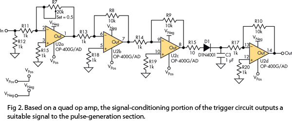
This version of the trigger circuit for the stop-motion camera system utilizes an electret microphone for sonic input, although it can be replaced with an LED and photodiode pair for optical triggering. A recent home-built project involved constructing a...
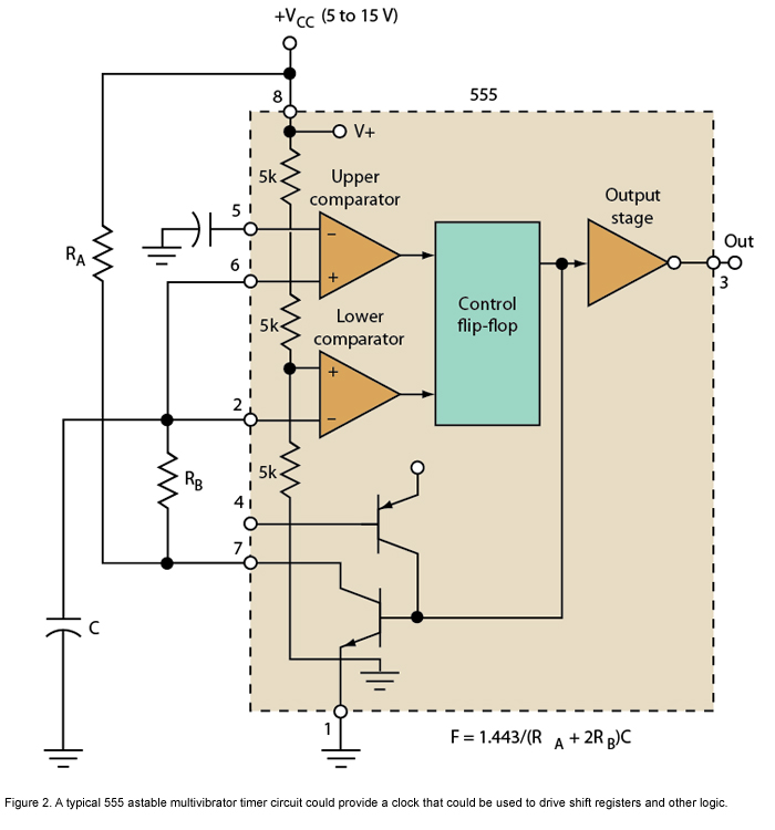
Micro or analog? These days, it is becoming increasingly challenging to make a choice. The 555 timer has long been regarded as a benchmark for flexibility. How does it perform today? The 555 timer IC, originally introduced in 1972, remains...
Inquiring about a simple method to bypass the tone controls in the preamplifier, with the understanding that a feedback circuit may be involved, leading to uncertainty. To bypass the tone controls in a preamplifier, one common method is to modify...
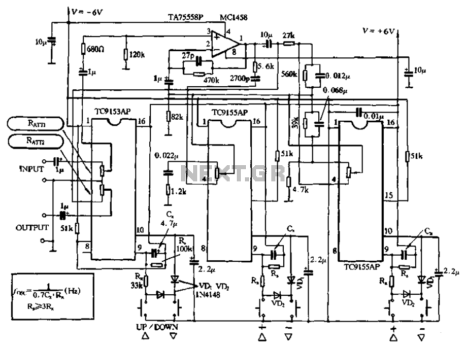
Figure 4-18 illustrates a volume potentiometer T (Xi 153AP) and a tone potentiometer T (155AP) that make up a volume and tone control circuit. This circuit includes Rx and Cx as clock oscillation elements, with values selectable based on...
A schematic representation of the SASS 2400 is shown in Figure 2 below. The cyclone has four main sections: a cyclonic cup, stripping column, cistern, and water feedback loop. A high-efficiency, brushless centrifugal blower at the cyclone exit pulls...

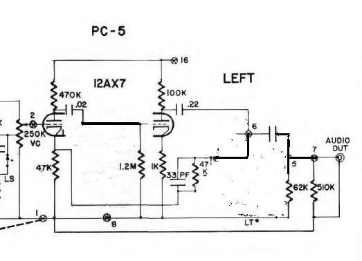
The LM386 amplifier section has been constructed and operates effectively. A five-conductor headphone jack has been acquired, which allows the left and right channels to connect to the mono amplifier when no headphones are plugged in, but disconnects the...