
mixing and volume

The LM386 amplifier circuit is a low-power audio amplifier designed for various audio applications, particularly in battery-operated devices due to its low supply voltage requirements. In this configuration, the amplifier's output can be directed to headphones or a speaker, depending on whether the headphone jack is engaged. The five-conductor headphone jack serves a dual purpose: it connects the audio signals while also providing a mechanism to disconnect the amplifier when headphones are inserted.
The mixing of the three audio channels from the AY-3-8913 is a critical aspect of the design. Each channel's output must be appropriately mixed to achieve the desired stereo effect. The resistor network plays a vital role in this mixing, as it determines the level of each channel that reaches the left and right outputs. The challenge lies in balancing the resistances to maintain a clear stereo separation while allowing for volume control through the potentiometer.
The use of a potentiometer introduces an additional layer of complexity, as adjustments to volume can inadvertently affect the mixing ratios. The analysis of resistance values illustrates how the potentiometer's position alters the overall impedance seen by each channel, which can lead to undesired audio characteristics.
To mitigate these issues, the implementation of a voltage follower configuration using either a transistor or an operational amplifier can be beneficial. By placing this component before the potentiometer, the mixing network's integrity can be preserved while still allowing for effective volume control. This solution would require careful consideration of the circuit layout and component values to ensure optimal performance without introducing additional noise or distortion.
In summary, the design of this audio amplification and mixing circuit necessitates a careful balance between channel mixing and volume control, with potential solutions involving strategic component placement and circuit design adjustments to achieve the desired audio output quality.I built the LM386 amplifier section, and it pretty much works. I purchased a five-conductor headphone jack, which passes the left and right channels through to the mono amplifier section when nothing is plugged in, but disconnects the amplifier section when a headphone plug is inserted. The only problem is that even when disco nnected, the amplifier section still picks up a faint copy of the audio signal (from antenna effects or power supply noise ) and amplifies it. Ideally the amplifier section would be switched off entirely when a headphone plug is inserted, instead of merely disconnecting its input signal.
The bad news: The portion of the circuit before the headphone jack seems able to mix three channels into two, or to control the volume, but not both. The AY-3-8913 has three separate voices: A, B, and C. I want to mix them so that A is on the left stereo channel, C is on the right channel, and a half-volume copy of B is on both channels.
This job is done with a resistor network. I also want to control the output volume with a potentiometer. Below are two similar circuits for performing these tasks. Although it`s not shown here, both circuits have their L and R outputs connected to the headphone jack, which in turn is connected to the speaker amplifier section as described above. On the right is the Polish circuit I mentioned in my last post, with a 10K stereo audio potentiometer added at the output.
On the left is a circuit I found on a ZX Spectrum hacking site, also with an output potentiometer. Neither circuit included a potentiometer originally. You can probably see where this is going: the functions of mixing and attenuation conflict. Mixing works because the total resistance between A, B, or C and L or R is different for different paths. In the case of the Polish circuit (right side), if the potentiometer is turned all the way so there`s zero resistance between input and output, then the total resistance from A to L is 1K, from B to L is 2.
2K, and from C to L is 5. 4K. There more than 5x the resistance for C to L versus A to L, so A appears mostly on the left channel, and very little of C appears on the left channel. If the potentiometer is now turned almost to the other extreme, so there`s 9K resistance between input and output, the situation changes.
Now there the total resistance from A to L is 10K, from B to L is 11. 2K, and from C to L is 14. 4K. These are all similar enough that all voices go to both channels more-or-less equally, and the stereo effect is lost. This is where I`m stuck: I can get stereo mixing, or volume attenuation, but not both at the same time.
The circuit on the left uses larger resistors, so the loss of stereo is less pronounced, but the maximum volume level is quieter. Move the potentiometer to after the headphone jack. This would allow for volume control of the amplified speaker, which is mono anyway, but the headphone jack would always be at maximum volume.
In practice this would make the jack only useful as a line-out, and not for headphones. Change the stereo mix so that A and B go to the left channel, and C to the right, with no common path between them. This is simple but non-symmetrical, and the 100% stereo separation may not sound very pleasing. Use a transistor or op-amp as a voltage follower, inserted before the potentiometer, so that changes in the potentiometer resistance don`t affect the resistor network used for stereo mixing.
This might be the best solution, but I`m uncertain how to build it, and don`t want to add still more elements to an already large circuit. 🔗 External reference
Related Circuits
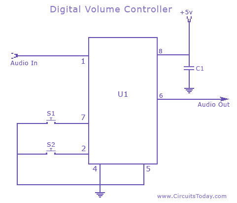
The circuit is a preamplifier with digital regulation intensity of sound. It is separated into three departments. The first schematic (Fig.1) shows the control circuit of the electronic potentiometer. The control is achieved through two pressing switches. The S1...
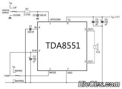
An amplifier with digital volume control can be designed predictably due to the simplicity of the circuit, which utilizes a single chip, the TDA8551. This series of mini amplifiers with digital volume control operates as a BTL (Bridge-Tied Load)...
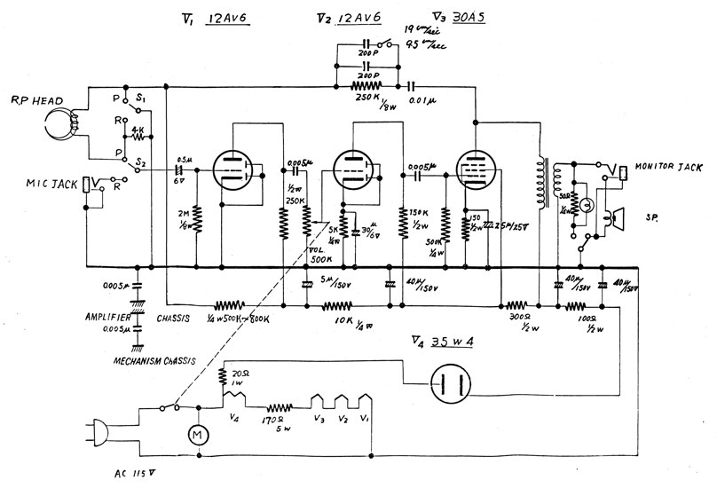
A Fujiya FL-555 audio recorder is experiencing issues with low volume output, even when the volume is set to maximum. The device was functioning correctly prior to this problem. The Fujiya FL-555 is a compact audio recorder designed for high-quality...

This is a BTL (bridged tied load) mono amplifier with a DC volume control circuit. This circuit utilizes the TDA7052A/AT, which is suitable for monitors, TVs, and battery-operated portable radios and recorders. Unlike conventional DC volume circuits, the TDA7052A/AT...
A digital volume control circuit diagram utilizing the DS1669, a potentiometer integrated circuit. This circuit can serve as a digital volume controller for audio amplifiers and various other applications. The digital volume control circuit employs the DS1669 integrated circuit, which...
AVC - The circuit regulates the volume line automatically, providing an output voltage of approximately 4 volts peak to peak. This voltage remains consistent. The Automatic Volume Control (AVC) circuit is designed to manage audio levels dynamically, ensuring a stable...