
Bi-Color Indicator Circuit

In this circuit, a bi-color LED serves the dual purpose of indicating when the circuit is powered and the status of switch SI, effectively functioning as two indicators.
The described circuit utilizes a bi-color LED to provide visual feedback regarding the operational status of the circuit and the position of switch SI. The LED consists of two elements: a green LED and a red LED, which are integrated into a single package. The circuit's design leverages the properties of bipolar junction transistors (BJTs) to control the LED's behavior based on the state of switch SI.
When the switch SI is in the open position, the voltage divider formed by resistors R2 and R3 ensures that a sufficient base voltage is applied to transistor Q2. This action turns on Q2, allowing current to flow through the green LED element, thus illuminating it. The illumination of the green LED serves as an indicator that the circuit is powered and operational.
Upon closing switch SI, the current flowing through resistor R1 provides base bias to transistor Q1. This results in Q1 turning on, which effectively grounds the voltage divider consisting of R2 and R3. As a consequence, Q2 is turned off, leading to the cessation of current through the green LED. The change in current flow results in the red LED element being activated, indicating that the circuit is under power and that switch SI is engaged in controlling another circuit.
The bi-color LED's functionality is enhanced by the use of BJTs, which allow for reliable switching and clear visual indications of the circuit's status. This design is particularly useful in applications where it is essential to monitor both power status and the state of control switches, providing a compact and effective solution for circuit indication. With SI open, base bias is supplied to Q2 through a voltage divider (formed by R2 and R3), thus turning on the green element in the LED. That indicates that power is being supplied to the project. If you close SI, current through R1 biases Ql on, thereby grounding the voltage divider and turning off Q2.
That reverses the flow of current through the LED, which causes its red element to light. That indicates that the circuit is under power and SI (really a DPDT switch), whose remaining section controls another circuit, is active. In this circuit, a bi-color LED is used to indicate when a circuit is under power and the status of SI. In that way, the LED does the job of two indicators.
Related Circuits
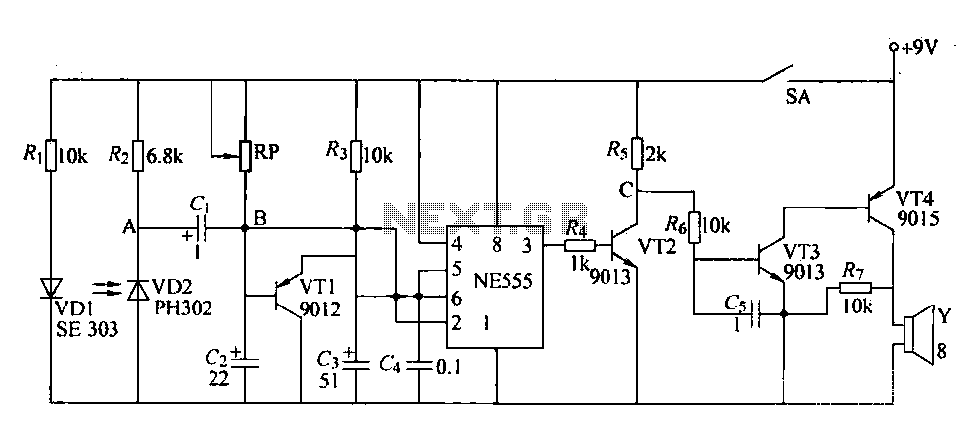
The circuit is designed to detect clogging in a wheat planter by utilizing light-emitting diodes (LEDs) and photodiodes. When the light path is obstructed by particles, the photodiode receives less light, causing the resistance of VD2 to increase. This...

The circuit is built around a single 4093 quad 2-input NAND Schmitt trigger. Two gates from that quad package (U1-a and U1-b) are configured as a set-reset flip-flop. The 4093 integrated circuit (IC) contains four independent 2-input NAND gates with...
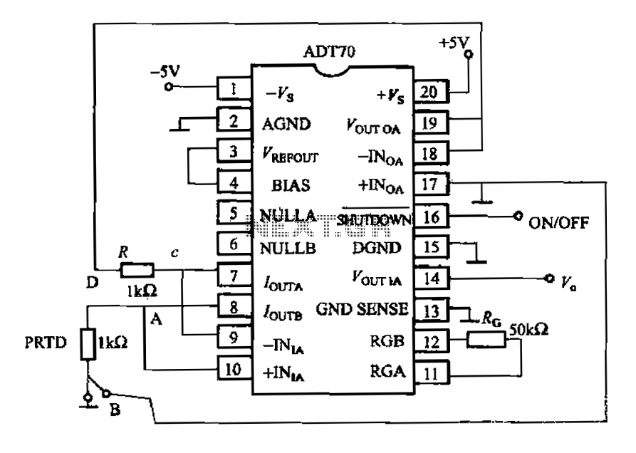
The AD170 basic electrical parameters include a temperature coefficient of 25 ppm/°C and a temperature measurement accuracy of ±1°C, with a maximum temperature range of -200°C to +100°C. The power supply required is +5V or -5V, and the operating...
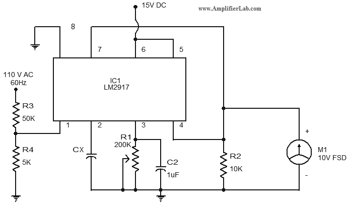
The circuit diagram of a simple capacitance meter is presented here. The primary component of this circuit is the frequency-to-voltage converter. The simple capacitance meter circuit utilizes a frequency-to-voltage converter as its central element to measure capacitance values. This circuit...
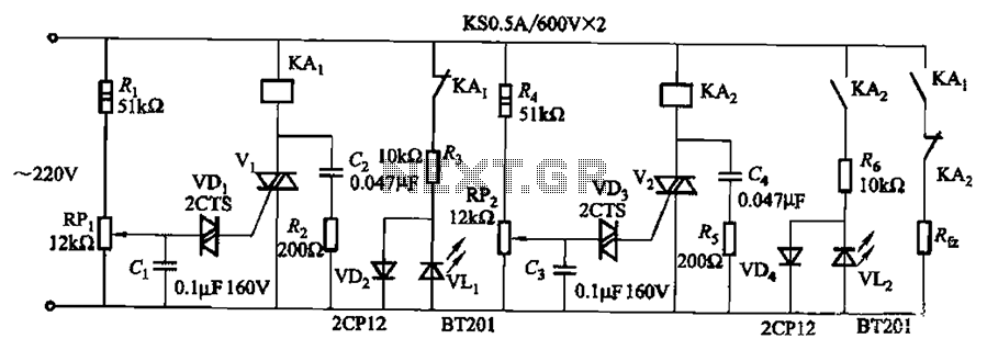
Bidirectional thyristor control. By adjusting potentiometers RPi and RPz, the lower and upper limit values can be changed. LEDs VLi and VL2 serve as indicators for low pressure and high pressure, respectively. The circuit utilizes a bidirectional thyristor to control...
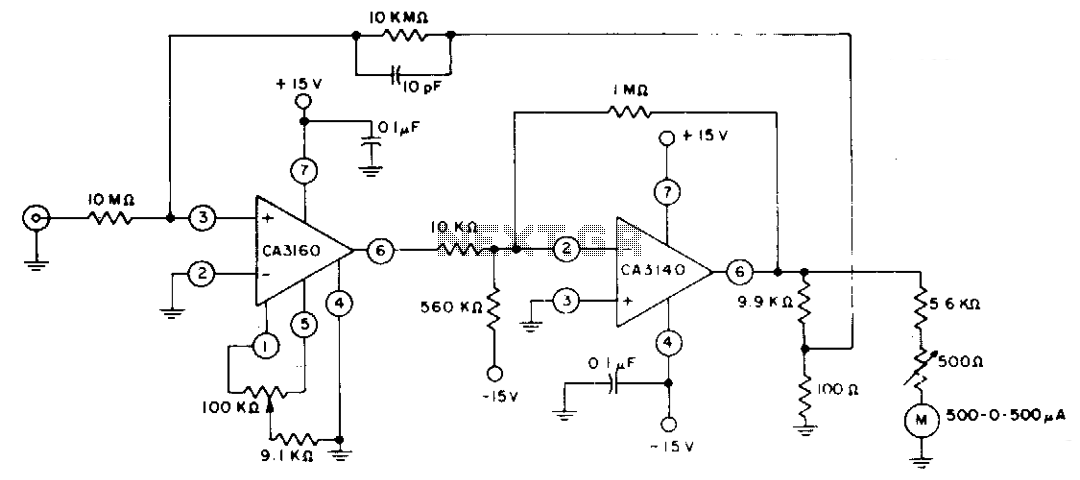
The circuit employs CA3160 and CA3140 BiMOS operational amplifiers to achieve a full-scale meter deflection of ±3 pA. The CA3140 functions as a 1T0 gain stage, supplying the necessary positive and negative output swing for the meter and the...