
Bicycle Radio easy and cheap to build (April 1940)
")
The described bicycle radio receiver circuit is a compact and efficient design, ideal for mobile applications. The use of a battery-operated, four-tube architecture minimizes weight while maximizing performance. The integration of a loop antenna with a metal rod enhances directional reception, making it suitable for urban environments where interference may be prevalent. The midget two-gang tuning condenser allows for precise tuning across local stations, enhancing user experience.
The choice of components, such as the Type 1N5GT and 1T5GT tubes, reflects an emphasis on sensitivity and power efficiency, crucial for battery-operated devices. The audio amplification stages ensure that the sound output is sufficient for outdoor environments, while the resistance-coupled design maintains signal integrity.
Grounding through the bicycle frame not only improves signal reception but also aids in reducing noise and interference, which is particularly important in mobile applications. The thoughtful arrangement of the battery system, including plug-in types for easy replacement, adds to the practicality of the design.
Finally, the implementation of a key-lock switch enhances user safety by preventing unintended battery drain, ensuring that the device remains functional when needed. This combination of features makes the bicycle radio receiver a well-engineered solution for enthusiasts seeking to enjoy radio broadcasts while on the move.This article by Arthur C. Miller was issued on page 88 to 90 in the book "Radio For The Millions" (prepared in 1945 by Popular Science Monthly staff, but first published in "Popular Scienece Monthly" April 1940). Fans who would like to install a radio on their bicycles so they can enjoy their favorite programs while riding around town or on short
trips will find the inexpensive set described on these pages just what they have been looking for. Fitting in a basket mounted on the handlebars, the battery-operated, four-tube receiver contains its own loudspeaker. It gives excellent results on local broadcast stations, and if iron-core coils instead of the air-space type specified are used this range will be increased.
Owing to the directional properties of a loop antenna, a 4` metal rod was chosen instead. The metal rod is connected directly to the grid cap of the radio-frequency tube. Both of the set`s coils are tuned by a midget two-gang tuning condenser, which is mounted on the sloping panel by means of two right-angle brackets. The antenna rod is insulated from the metal cabinet by a ceramic stand-off insulator. The tops of these insulators are usually threaded, and the best method of attaching the aluminum rod is to thread it to fit, and screw it into the insulator.
For greater signal strength, the set will have to be grounded. The bicycle frame provides excellent counterpoise capacity for this purpose. Keep tuned as you ride with this receiver. Note how the tubes are mounted on aluminum chassis, the speaker on the sloping panel, and how the batteries are arranged in the cabinet. The steel cabinet used for housing the chassis and batteries measures 6 ½" by 7" by 11" and is small enough to fit inside a standard-size bicycle luggage basket.
The panel is attached to the cabinet by means of self-tapping screws. The two "B" batteries that fit inside the cabinet along the back are the new small-size portable type employing the special flat cells with expanding seals. A 1 ½-volt "A" battery fits in between the two "B" batteries, with the 4 ½-volt "C" battery directly in front of it.
The "A" and "B" batteries are of the plug-in type and use clip-in plugs with Fahnestock terminals. This system makes it an easy matter to change batteries whenever necessary. In order to obtain ample volume from the speaker, two stages of audio-frequency amplification are used after the detector. Both stages are resistance-coupled and use the latest-type tubes for maximum sensitivity. Type 1N5GT tubes are used in the radio-frequency, detector, and first audio-frequency stages. A beam power tube, 1T5GT, is used in the output stage, and provides a relatively high output with a very low filament drain.
A 15, 000-ohm, ½-watt resistor is used in the grid circuit for the first audio tube. Any increase in value of this resistor will only cause instability and will fail to increase the amplification. Volume is controlled by a 100, 000-ohm potentiometer placed in the screen circuit of the radio-frequency tube.
The key-lock switch is of the double-pole, single-throw type and breaks two circuits at one time, the positive "A" supply and the ground lead of the volume control. This is done to avoid any drain through the "B" supply while the set is turned off. 🔗 External reference
Related Circuits

The Nora K5W is a German radio from about 1929/1930. It uses the tubes: 2x REN804, 2x REN1004, RE134 or RE604, RGN1054. The Nora K5W radio receiver represents a significant piece of technology from the late 1920s, showcasing the early...

BattMan II is a computer-controlled battery manager designed for typical rechargeable batteries utilized by R/C and electronics hobbyists, as well as various consumer product batteries. BattMan II supports Nickel-Cadmium (NiCd), Nickel-Metal-Hydride (NiMH), Lithium-Ion (Li-Ion), Lithium-Polymer (LiPo), Lithium-Nano-Phosphate (LiNP), and...
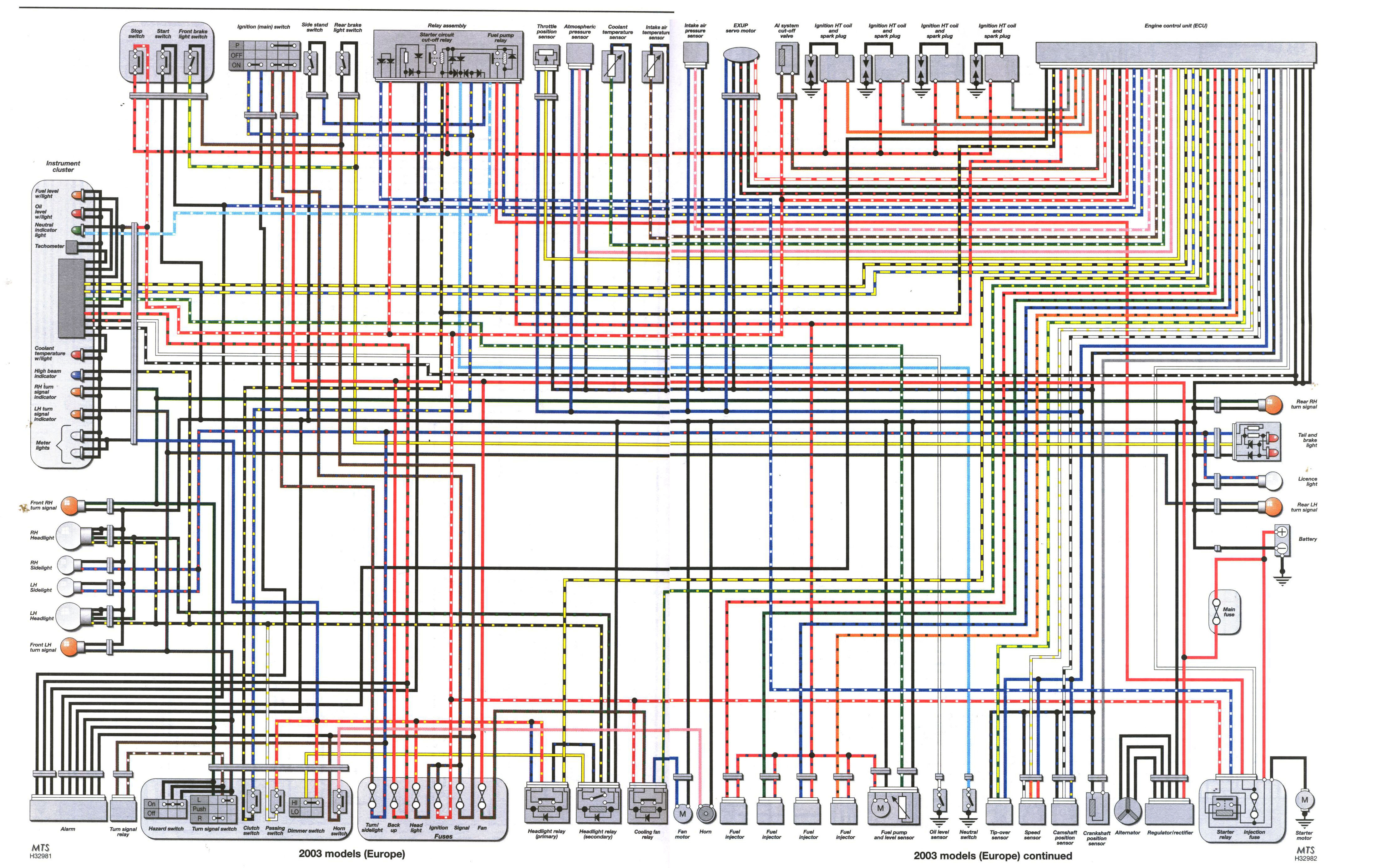
The plumbing and fuel system installations are complete, and final checks on the electrical system are currently in progress. The bike loom is being tidied up and tested. There is a query regarding two unused connectors in the 2003...
The ZN414 integrated circuit (IC) contains a complete automatic gain controlled AM receiver within a compact three-pin package. With only a few external components, it is possible to construct a simple radio that offers excellent selection and reception capabilities....
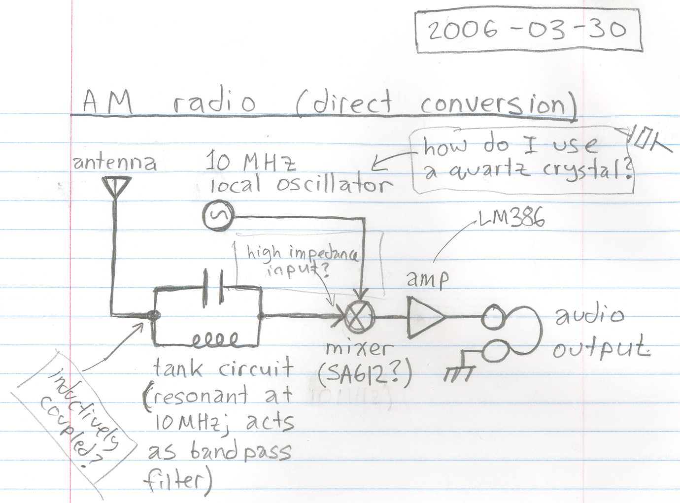
A basic design for a direct conversion AM radio receiver is being developed. "Direct conversion" refers to the technique of utilizing a mixer to shift the radio frequency signal down to baseband audio frequencies. There are uncertainties regarding the...
A varying brightness AC lamp circuit utilizes a silicon-controlled rectifier (SCR) to gradually adjust the intensity of a 120-volt light bulb by controlling the duration of AC line voltage applied to the lamp during each half cycle. The circuit...