
Build a Computer Controlled Battery Manager

The BattMan II schematic integrates multiple components to achieve its functionality as a battery manager. The design includes a microcontroller interfacing with the parallel printer port to interpret data signals from the computer. The R-2R ladder network constructed from CMOS buffers and resistors serves as the primary digital-to-analog converter, translating digital signals into a precise voltage output for battery management. The output voltage is crucial for the accurate charging and discharging of various battery types, ensuring they operate within their specified voltage ranges.
The use of op-amp Z4a is integral to the circuit, as it allows for the fine-tuning of the current flowing through the power resistor R45, which acts as a sensing element. The TIP120 transistor Q3 provides the necessary amplification to control higher currents required for charging the batteries, making the circuit efficient and responsive to the varying demands of different battery chemistries. The careful selection of components and their arrangement in the schematic reflect a well-thought-out design, aimed at providing hobbyists and professionals with a reliable tool for battery management.
This project not only emphasizes the importance of understanding electronic principles but also showcases the application of those principles in real-world scenarios, such as battery maintenance and performance enhancement. The detailed construction and calibration instructions included in the documentation ensure that users can replicate the setup with confidence, leading to successful project outcomes.BattMan II is a computer controlled battery manager, intended for typical rechargeable batteries used by R/C and electronics hobbyists, as well as various consumer product batteries. BattMan II has the following capabilities: Works with Nickel-Cadmium (NiCd), Nickel-Metal-Hydride (NiMH), Lithium-Ion (Li-Ion), Lithium-Polymer (LiPo), Lithium-Nano-P
hosphate (LiNP), and Lead-Acid (Pb-Acid) batteries of 1. 2 to 14. 7 Volts. Requires sufficient memory to comfortably run Windows, a few megabytes of free hard disk space, and 800G—600 or higher resolution display. If you want to modify the software, you`ll also need Borland C+ Builder 5 or newer. BattMan II is a fairly complex project, and this article assumes that you have some electronic project building experience.
If you`re reasonably careful in construction and follow the testing and calibration instructions closely, you should have no problems getting it to work. Your success with this project will benefit from an understanding of how it works, so please read the next section carefully before you plug in the soldering iron.
If you don`t want to build this project but need a device like this for your consumer electronics batteries, you might consider the La Crosse Technology BC-1000 AlphaPower Battery Charger or Maha Powerex MH-C9000 WizardOne Charger-Analyzer. This performs many of the same functions as BattMan II, but only for AA and AAA NiCd or NiMH cells (up to four at a time).
The La Crosse charger also comes with adapters to let you use AAs in devices requiring C or D sized cells. The power supply I used is a commercial off-the-shelf model that can supply 18 Volts at 2. 2 Amps. I purchased mine at a surplus store. Any similar power supply will do, so long as it produces 18 to 20 Volts, and enough current for the maximum charge rate you want to be able to use.
Points labeled V+ in the schematic are connected to the positive terminal of the power supply. CMOS buffers Z2a through Z2d together with resistors R26 through R34 form an R-2R ladder digital-to-analog converter. R34 is used to adjust the output voltage range so that it spans 0 to 0. 2 Volts (which can be measured at test point TP2). The input to the converter is taken from the four low-order data bits (D0 to D3) of the parallel printer port that BattMan is connected to.
I built my original (unpublished) BattMan computer controlled battery manager in 1995. I had been wanting to build it for a year or so but never found the time. Then one day, one of our customers asked if there was anything we could do about the performance of his aging laptop NiCd battery. This provided the impetus to finally build it, and I successfully used it to test and rejuvenate the battery.
I planned to write a construction article at that time but it never happened. Eventually the original BattMan became obsolete, primarily because it needed a computer running DOS, which was getting rare. Around 2000 I decided it was time for BattMan II, but BattMan I was still working fine so I had no real need for a newer version.
Then, in 2007 we started looking at the power consumption of all the old PCs we still kept running for various reasons. One was used for nothing except operating BattMan I and we determined that it`s standby power consumption was 330kWh per year ($40 per year on our electricity bill).
That was enough reason to build BattMan II, which could be connected to one of our necessary computers instead of hogging a whole computer to itself. The output of this D-to-A converter is fed into op-amp Z4a, which together with Q3 (a TIP120 NPN Darlington transistor) and R45 (a 0.
1 © power resistor) forms a constant current sink. Z4a adjusts the base current to Q3 so that the voltage across R45 remains equal to the voltage from the D-to-A converter. The effect is that there will be a constant current flowing into the collector of Q3 (since a constant voltage across a resistor requ
🔗 External reference
Related Circuits
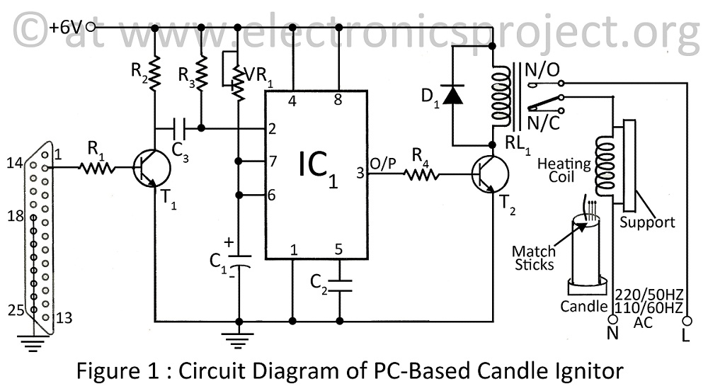
A PC-based candle ignitor is a verified project designed for computer students, utilizing a 555 timer circuit to ignite a candle. The project includes a computer circuit diagram and software code written in C. The PC-based candle ignitor project integrates...
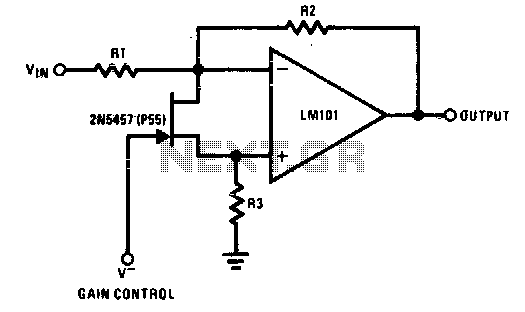
The 2N5457 functions as a voltage-variable resistor with a maximum RdS of 800 ohms. Given that the differential voltage on the LM101 is in the low millivolt range, the 2N5457 JFET exhibits linear resistance over several decades, offering excellent...
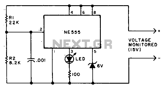
Due to the low duty cycle of the flashing LED, the average current drain is 1 mA or less. The NE555 will trigger the LED when the monitored voltage falls to 12 volts. The ratio of R1 to R2...
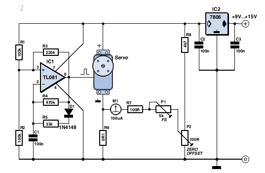
With some skill, an electronic scale can be constructed using a servo motor. Depending on the servo type, it can measure weights of up to approximately five kilograms (11 lbs) with reasonable accuracy. A detailed examination of the operating...
Switch mode circuits can implement a lead acid battery charger more efficiently. It can be constructed using the bq24105 battery charger controller. The bq24105 was originally designed to charge single, two, or three-cell Li-polymer and Li-ion battery packs. However,...
The two optical sensors will provide a count of individuals to the microcontroller, which will relay this value to MCU-II. The microcontroller will detect the entrance of any person through high-to-low pulse transitions on input pins A3 and A4. The...