
Photo Switch Circuit

The described circuit utilizes the NE 555 timer IC configured in a comparator mode to create a photo switch that responds to varying light levels. The NE 555 is a versatile and widely used integrated circuit that can operate in different modes, including astable, monostable, and bistable configurations. In this application, it is set up to function as a light-sensitive switch.
The circuit comprises a light-dependent resistor (LDR) that acts as the light sensor. The resistance of the LDR decreases as light intensity increases, which alters the voltage at the non-inverting input of the NE 555. A reference voltage is established at the inverting input using a voltage divider formed by resistors. When the light intensity falls below a predetermined threshold, the voltage at the non-inverting input drops below the reference voltage, triggering the NE 555 to output a high signal.
This output signal is then used to drive a relay. The relay serves as a switch to control larger loads, such as lamps or industrial equipment, allowing them to be turned on or off based on the ambient light conditions. The circuit can be further enhanced by incorporating additional components such as capacitors for noise filtering and diodes for flyback protection across the relay coil.
The schematic diagram would typically show the connections between the LDR, NE 555, resistors, and relay, providing a clear visual guide for assembly. The simplicity of this circuit makes it an excellent choice for automatic lighting systems in both residential and commercial settings, ensuring energy efficiency and convenience.A simple photo switch circuit using NE 555 IC with diagram and schematic.This photo switch ons a relay when light intensity crosses limit.A light sensor circuit for home and industrial purpose 🔗 External reference
Related Circuits
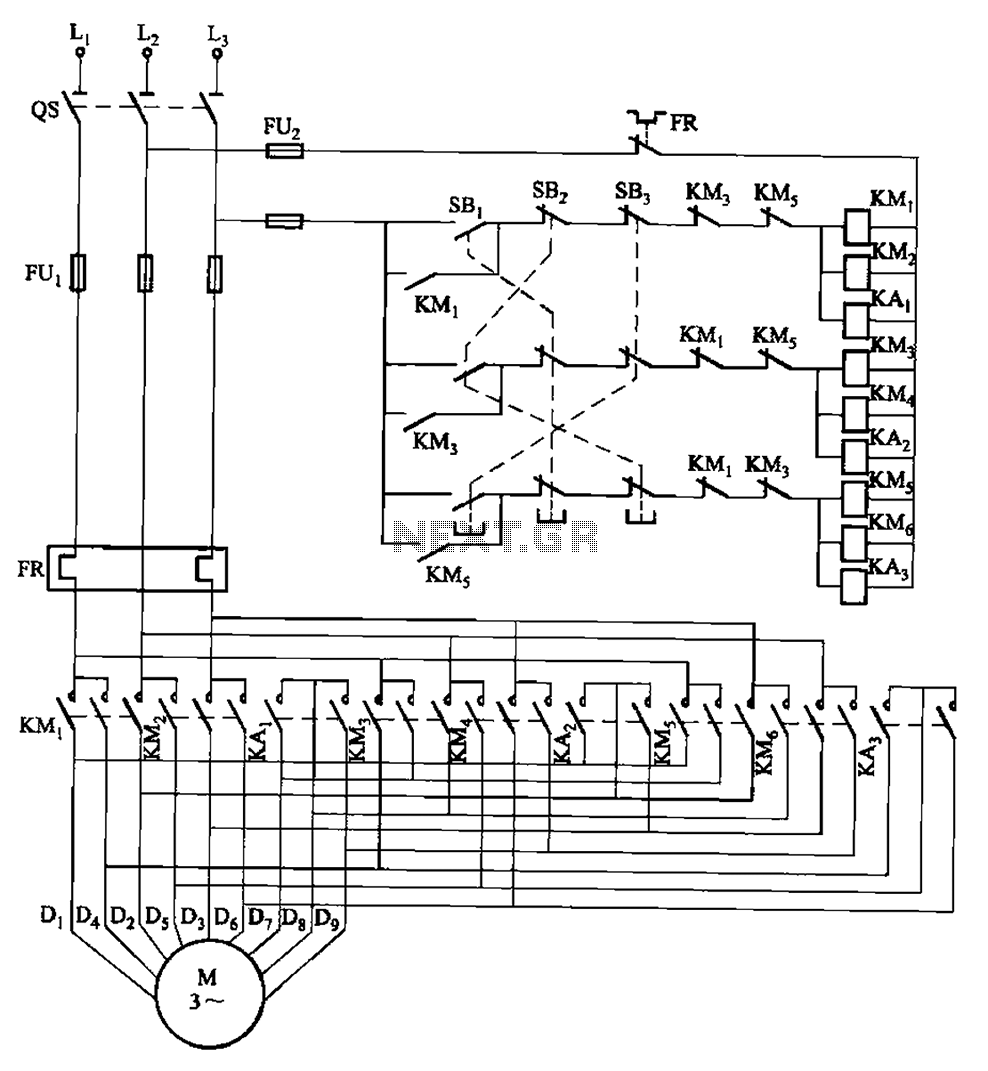
The circuit depicted in Figure 3-115 utilizes contactors and double buttons, allowing for speed conversion without the need to press the stop button. The buttons SBi, SBz, and SB3 correspond to high, medium, and low-speed operation, respectively. This circuit design...
There are many circuits for low voltage regulators. For higher voltages, such as supplies for valve circuits, the situation is different. Low voltage regulators are widely utilized in electronic circuits to provide a stable output voltage from a varying input...
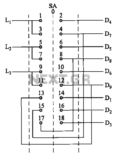
The motor switch control circuit depicted in the figure provides two speed settings for counter-steering, allowing for operation at two speeds in opposite directions. The motor switch control circuit is designed to facilitate the operation of a motor at two...
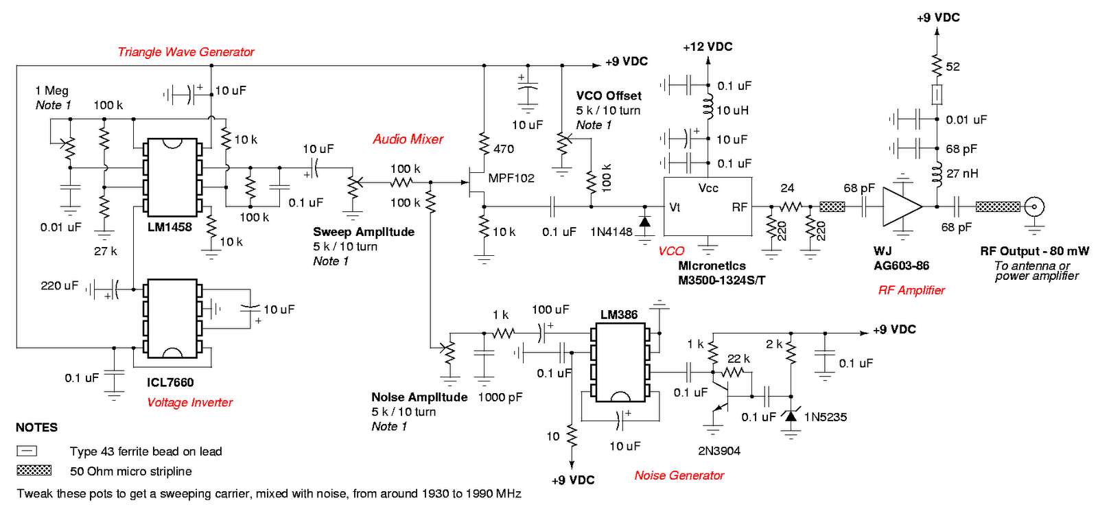
An admirable DIY GSM jammer or cellular mobile phone jammer schematic diagram designed for use with GSM1900, operating within the frequency range of 1930 MHz to 1990 MHz. The GSM1900 cellular mobile phone system is utilized in the USA,...
This amplifier is designed to be self-contained within a compact loudspeaker enclosure. It can be powered by devices such as Walkmans, Mini Discs, iPods, CD players, computers, and other devices equipped with line or headphone outputs. Typically, two units...

This is a circuit design for a doorbell that produces a bird-like sound. The circuit is controlled by an NPN transistor. The operation of the circuit begins when P1 is set to an experimental value, starting with approximately 220...