
NiCAD Battery Charger with Current and Voltage Limiting

This Ni-CAD battery charger circuit is designed to ensure safe and efficient charging of nickel-cadmium batteries. The key components of the circuit include a transformer, rectifier, voltage regulator, current limiting resistor, and indicator lamps.
The transformer steps down the mains voltage to a suitable level for charging the battery. Following the transformer, a rectifier converts the AC voltage to DC, which is necessary for charging the battery. The rectified output is then smoothed using a capacitor to reduce ripple voltage, providing a more stable charging voltage.
Current and voltage limiting features are critical in preventing overcharging, which can damage the battery and reduce its lifespan. A current limiting resistor is included in the circuit to restrict the maximum current flowing to the battery. Additionally, a voltage regulator may be employed to maintain a consistent output voltage, ensuring that the battery does not exceed its rated voltage during the charging process.
The indicator lamp L1 provides a visual indication of the charging status. When the charger is actively charging the battery, L1 will illuminate brightly, signaling that the circuit is functioning correctly. Conversely, an LED indicator will be off when the battery is fully charged, indicating that charging has ceased to prevent overcharging.
Overall, this schematic diagram presents a comprehensive solution for charging Ni-CAD batteries safely and effectively, extending their operational life through careful management of current and voltage during the charging process.The following diagram is the schematic diagram of Ni-CAD Battery Charger circuit which featured with current and voltage limiting to keep the battery lifetime. The lamp L1 will be light brightly and the LED will be out when the battery is.. 🔗 External reference
Related Circuits
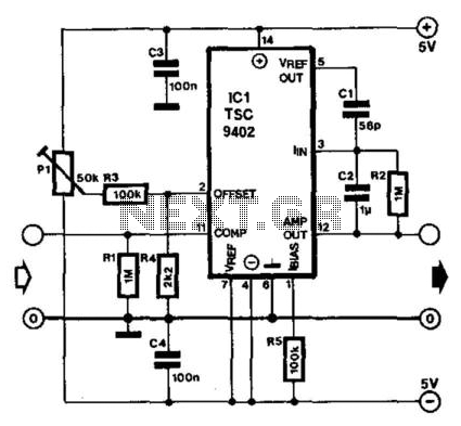
Teledyne Semiconductor's Type TSC9402 is a versatile integrated circuit (IC) capable of converting voltage to frequency and frequency to voltage. It is well-suited for use as an add-on unit for measuring frequencies with a multimeter, requiring only a few...
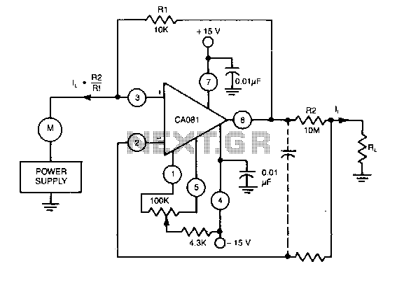
This circuit utilizes a CA018 BiMOS operational amplifier. A low current, supplied at the input potential as a power supply to the load resistor RL, is amplified by the resistor ratio R2/R1, while the load current h is monitored...
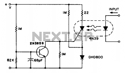
The SCR coupler circuit offers increased sensitivity to input signals as demonstrated. This enables the utilization of the more economical 4N39 (H11C3) with the drive currents exceeding 7 mA provided by the input circuit. The SCR coupler circuit is designed...
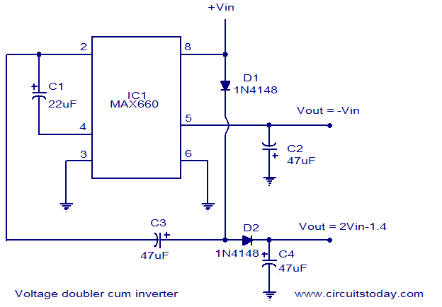
Voltage doubler circuit and voltage inverter circuit diagram with schematics using MAX660 IC, which is a DC voltage multiplier IC. This is a DC voltage doubler circuit and inverter. The MAX660 integrated circuit (IC) is designed for applications requiring a...
A simple NiCd charger can be constructed using commonly available components and an inexpensive LM317 or 78xx voltage regulator. The design incorporates a current limiter composed of resistor R3 and a transistor, allowing it to charge multiple cells until...
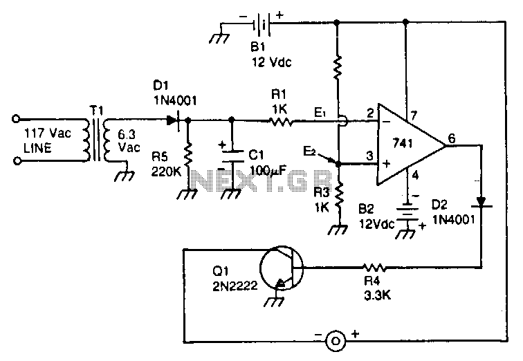
This circuit utilizes a type 741 operational amplifier (op amp) configured as a voltage comparator. One input of the 741 is connected to a reference voltage, sourced from a 12-V battery, via a resistor voltage divider. The voltage at...