
Biomedical Monitoring circuit AT89C2051

The described project focuses on the design and implementation of a generic real-time wireless communication system, addressing the limitations of existing commercial wireless monitoring systems. The circuit schematic for such a system typically includes several key components: a microcontroller, wireless transceiver modules, sensors, and a power supply.
The microcontroller serves as the central processing unit, managing data acquisition from various sensors and controlling the wireless communication. Common choices for microcontrollers include the Arduino family or Raspberry Pi, which offer sufficient processing power and flexibility for real-time applications.
Wireless transceiver modules, such as those based on Wi-Fi (e.g., ESP8266/ESP32) or Bluetooth (e.g., HC-05), facilitate the transmission of data between the monitoring system and a remote user interface. These modules should be selected based on the required range, data rate, and power consumption.
Sensors play a critical role in the system, providing real-time data relevant to the monitoring application. Depending on the intended use, this could include environmental sensors (temperature, humidity), motion sensors, or specific industrial sensors. Each sensor must be connected to the microcontroller via appropriate interfacing circuitry, which may include analog-to-digital converters (ADCs) for analog sensors.
The power supply circuit is essential to ensure reliable operation of the system. It may include batteries or a power adapter, along with voltage regulators to provide stable power to the microcontroller and peripherals.
In addition to the hardware components, software development is crucial for the system's functionality. This involves programming the microcontroller to handle data collection, processing, and communication tasks, as well as developing an interface for users to interact with the system remotely.
Overall, the design and implementation of a real-time wireless communication system require careful consideration of hardware selection, circuit design, and software integration to create an effective monitoring solution.In spite of the improvement of communication link and despite all progress in advanced communication technologies, there are still very few functioning commercial wireless monitoring systems, which are most off-line, and there are still a number of issues to deal with. Therefore, there is a strong need for investigating the possibility of design and implementation of an interactive real-time wireless communication system. In our project, a generic real-time wireless communication system was designed and developed for sh 🔗 External reference
Related Circuits
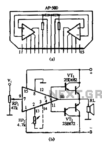
The AP500 is a high-performance dual-channel FET DC amplifier driver module designed for high operating voltage applications. It features push power, low distortion, a wide frequency response, and a simple external circuit. Utilizing superior resistance characteristics in audio circuits,...
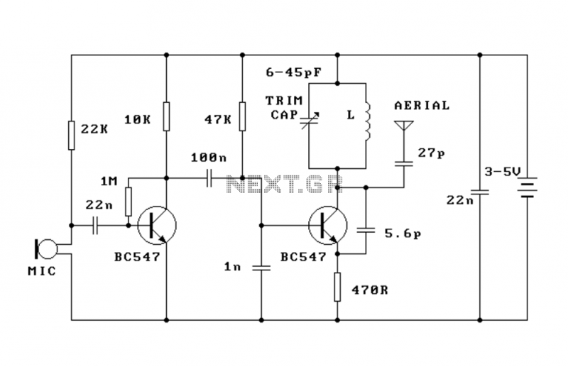
This FM transmitter (FM Tx) is about the simplest and most basic FM Tx it is possible to build and have a useful transmitting range. It is surprisingly powerful despite its small component count and 3V operating voltage. It...
The car parking sensor circuit utilizes a photodiode as the distance sensor. It measures the distance between adjacent sensors. The car parking sensor circuit employs photodiodes to detect the proximity of obstacles, enhancing parking safety and convenience. Photodiodes are semiconductor...
Many amplifiers have phono inputs for connecting record players to the amplifier. Phono input is designed to take a up to few millivolt signal from phono pickup and amplify it. The amplifier stage does also some equalization based on...
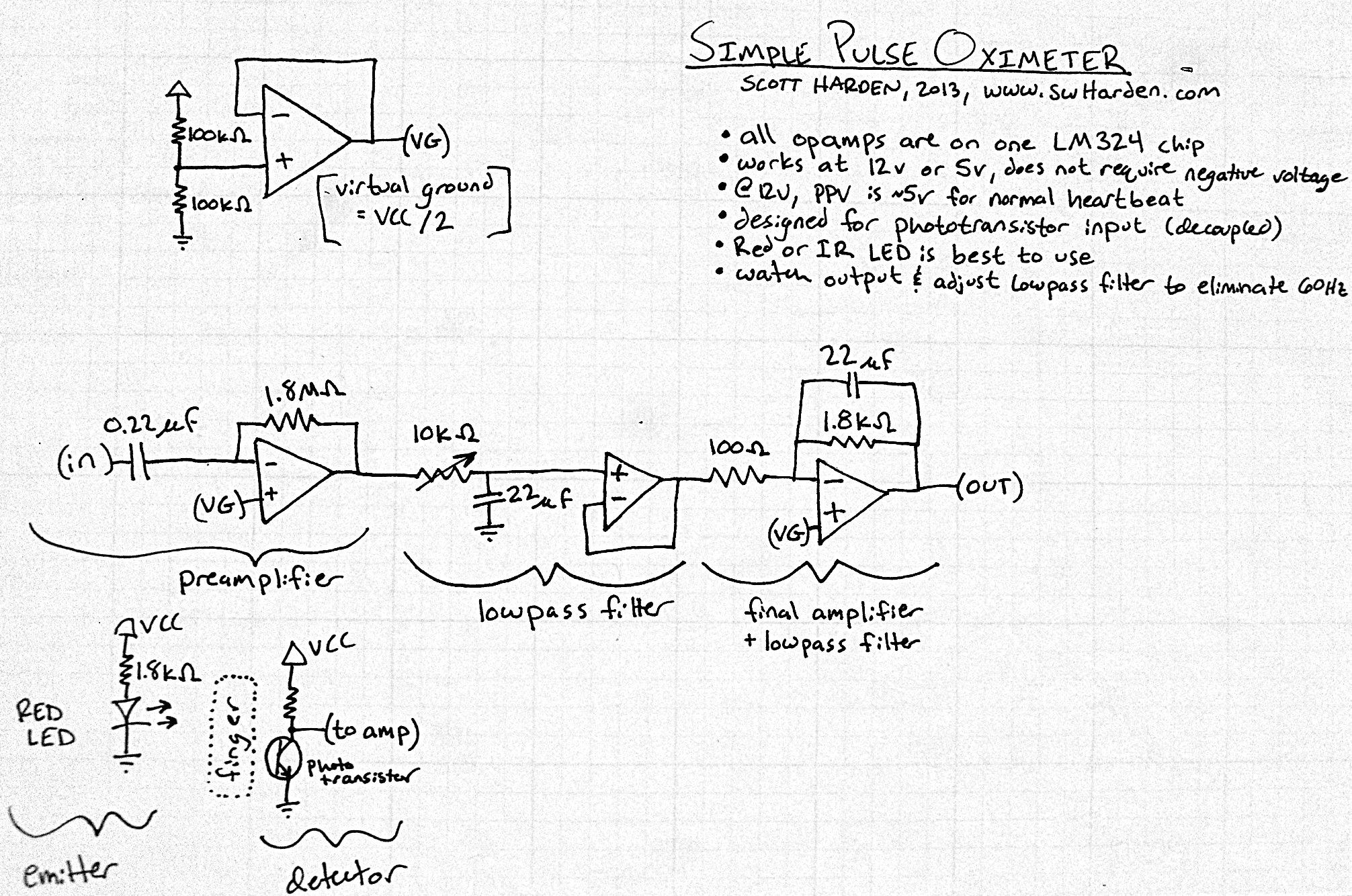
The input capacitor for the phototransistor at the bottom is responsible for feeding the operational amplifier (op-amp). However, the output from the phototransistor consistently remains between ground (GND) and the supply voltage (Vcc). The necessity for an input capacitor...
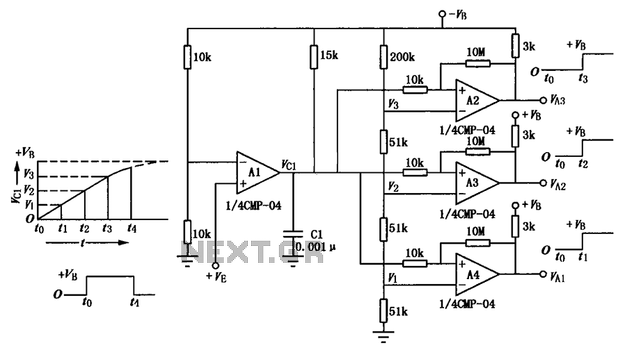
A multi-stage delay circuit is presented in this schematic. The operational amplifiers are configured as comparators. Operational amplifier A1 operates when the voltage at the inverting input exceeds + VE. As the voltage at the inverting input of operational...