
Line signal to phono adaptor circuit

The described circuit serves as a phono input converter, specifically designed to facilitate the connection of line-level audio sources, typically outputting signals between 0 to 1 volt, to phono inputs that require significantly lower signal levels, typically in the range of 0 to 5 millivolts. This conversion is essential for integrating modern audio equipment with legacy systems, particularly where phono inputs are concerned.
The circuit operates by performing two critical functions: signal level attenuation and inverse RIAA filtering. The attenuation process reduces the nominal input signal of 500 mV down to a nominal output of 2.5 mV, achieving an attenuation of 46 dB. This is accomplished through a resistive divider network that ensures the output signal is compatible with the phono input specifications.
Impedance matching is also a significant feature of this circuit. The input impedance is greater than 10 kΩ, which allows for minimal loading on the source device, while the output impedance is set at 470 ohms, ensuring compatibility with the following stage of amplification in the audio chain.
The inverse RIAA filtering network is integral to the circuit's design, as it compensates for the RIAA equalization typically applied to the audio signal during vinyl mastering. This filtering ensures that the frequency response of the audio playback remains flat, aligning with the original intention of the recording. The circuit's design allows it to accommodate both moving magnet and high-output moving coil cartridges, making it versatile for various audio setups.
The simplicity of the circuit allows for easy construction, enabling users to assemble it with basic soldering skills and minimal components. The circuit can be housed in a compact metal enclosure, with RCA connectors for straightforward integration into existing audio systems.
This design is a simplified adaptation of a previously published circuit, which indicates that while it may not utilize high-precision components, it is still deemed sufficient for general use, especially in applications where cost-effectiveness is a priority. The overall performance, while not on par with more complex designs, remains adequate for many audio applications, particularly for users seeking to repurpose unused phono inputs in modern audio environments.Many amplifiers have phono inputs for connecting record players to the amplifier. Phono input is designed to take a up to few millivolt signal from phono pickup and amplify it. The amplifier stage does also some equalization based on standardized RIAA curve. That RIAA equalization is used in the playback to reduce the high pitch noise and maximize bass dynamics in the phono playback. The audio material which is rocorded to the record has been pre-equalized so that the frequency response of the whole chain from the mixing desk to your speaker will give flat frequency response.
Nowadays phono inputs are largely unused because vinyl record players are getting rare. This circuit is is a simple converter to convert line level signal (0..1 V) to phono input levels (0..5 mV), which makes it possible to use those inputs as an extra line input. This circuit does the level conversion, impedance matching and inverse RIAA filtering. The inverse-RIAA filtering network in this circuit is needed, because all phono inputs have RIAA filter in them.
Input impedance: > 10 kohm Output impedance 470 ohms Nominal input signal level: 500 mV Nominal output signal level: 2.5 mV Attenuation: 46 dB Frequency response: inverse-RIAA Phono input compatibility: moving magnet and high output moving coil type inputs (= compatible with most receivers and integrated amplifiers). The circuit does two functions: signal level attenuation and inverse RIAA filtering. The signal attenuation is needed to convert the 500 mV signal to 2.5 mV signal. The inverse-RIAA filtering is needed to make the frequency response of the system flat (same equalization that is used when music is transferred to vinyl in the studio).
The picture blow shows the frequency response of the ideal inverse-RIAA filter: The picture below shows the circuit diagram of one channel. The other channel (for stereo) is identical. The circuit is so simple that you can easily build it by just soldering the components together and fit them to small metal box with the RCA audio connectors.
This circuit is a simplified version of circuit published in Elektor Electronics (T.Giesberts, Pick-up input becomes line input, Elektor Electronics, December 1995, page 99). The basic circuit idea is same, but my circuit is simpler and it does not use high-precision components.
The performance is not the same, but I think that this circuit build even from 5% components is adequate for many purposes. 🔗 External reference
Related Circuits
A Butterworth filter is a type of filter characterized by a frequency response that is flat within the passband region. This filter was first described by British engineer Stephen Butterworth. A Butterworth filter is designed to provide a maximally flat...
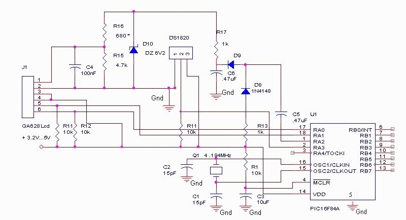
The DS18S20 digital thermometer offers a precision of 0.5 °C, with the SCRATCHPAD being read every 800 ms. Capacitors C5 and C6, along with diodes D8 and D9, form a voltage doubler to power the LCD panel. The DS18S20...
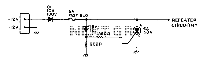
To protect portable emergency power repeaters from reverse or excessive voltage, diode D1 prevents damage from incorrect polarity, while the zener diode voltage sets the maximum voltage that can reach the rest of the circuitry. Additionally, a fast-blowing fuse...
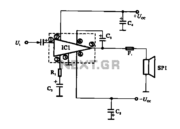
The OCL power amplifier circuit is an integrated circuit. Circuit IC1 is an integrated circuit, and its internal circuit configuration is substantially similar to the OTL power amplifier circuits. The OCL (Output Capacitor-Less) power amplifier circuit is designed to provide...
This circuit below shows a teleremote circuit that enables the switching on and off of appliances through telephone lines. The teleremote circuit utilizes a telephone line as a medium for controlling electrical appliances from a distance. The primary components...
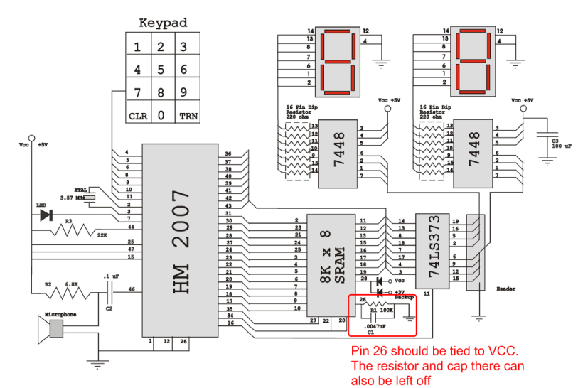
Verify the pin configurations on the datasheets for the integrated circuits used in your project, making necessary adjustments. In this instance, the RAM chip utilized had a non-inverted enable signal on pin 26, while the schematic assumed it was...