
Simple Car Parking Sensor circuit

The car parking sensor circuit employs photodiodes to detect the proximity of obstacles, enhancing parking safety and convenience. Photodiodes are semiconductor devices that convert light into an electrical current. In this circuit, they are strategically placed to measure the distance to nearby objects, such as other vehicles or barriers.
The operation of the circuit is based on the principle of light reflection. When an object enters the detection zone of the sensor, it reflects light back to the photodiode. The intensity of the reflected light correlates with the distance of the object; closer objects reflect more light, while those further away reflect less. The circuit processes this information to determine the distance between the vehicle and the detected object.
The design typically includes multiple photodiodes arranged in a linear or grid pattern, allowing for a wider detection area. Each photodiode is connected to a microcontroller or comparator circuit that interprets the signals received. The output can be used to activate visual or auditory alerts, such as LED indicators or beeping sounds, to inform the driver of the proximity of obstacles.
To ensure accuracy, the circuit may incorporate calibration routines that adjust the sensitivity of the photodiodes based on environmental conditions, such as ambient light levels. Additionally, the distance measurement can be fine-tuned by adjusting the placement of the sensors, ensuring optimal performance in various parking scenarios.
Overall, the car parking sensor circuit is a practical application of photodiode technology, providing a reliable solution for enhancing vehicle safety during parking maneuvers.car parking sensor circuit takes advantage of the photodiode as the sensor distance. The distance between adjacent sensors. 🔗 External reference
Related Circuits
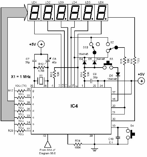
A digital audio frequency (AF) counter can be constructed using a minimal number of components by employing a single 7226B integrated circuit (IC) from Intensil, as depicted in the accompanying diagram. This circuit has an upper frequency limit of...
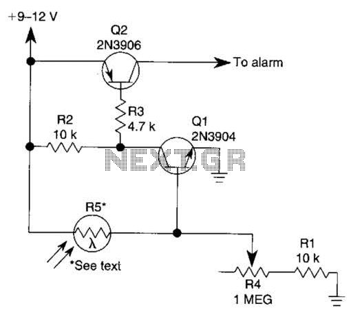
The circuit functions as a sensor capable of triggering an alarm without direct contact from an intruder. It utilizes a visible or invisible light source that illuminates the sensor, maintaining the detection loop in a normally closed state. As...
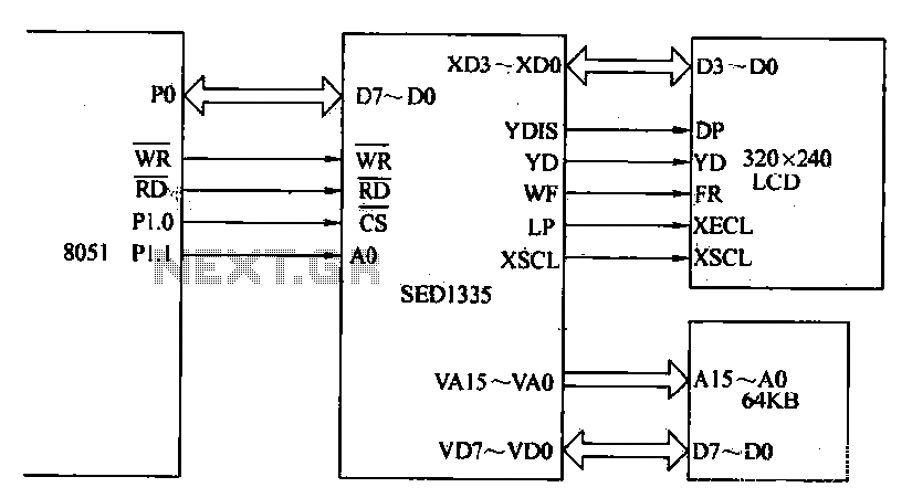
The MCS-51 series single-chip interface circuit 8051 is utilized to control the SED1335 35 dot matrix LCD display. This controller can manage up to a 640x256 dot matrix LCD display for both graphics and character representation, with the capability...
The circuit diagram illustrates a five-use tri-state audio logic pen utilizing components such as the CD4066 and a 555 timer. The primary elements include a multivibrator, a four-way switch (CD4066, designated as IC1), and a gate circuit formed by...

The circuit can be constructed using a pair of twin-T oscillators, with the Q factor adjusted to the threshold of oscillation, allowing them to resonate like a bell when activated by a voltage pulse. Each twin-T oscillator is designated...

This digital thermometer circuit diagram utilizes a standard 1N4148 diode as the temperature sensor. The temperature coefficient of the diode is -2 mV/°C. The digital thermometer circuit leverages the characteristics of the 1N4148 diode, which exhibits a predictable voltage drop...